

6. Touchscreen Driver
The previous lesson covered display output over HDMI, eDP, and MIPI. This lesson adds touch input so you can interact with the Android or Linux interface.
Video Tutorial
Lesson 6 — Touchscreen Drivers (Chinese)
Preparation
Lesson Overview
A touchscreen driver combines GPIO, interrupts, I²C, and the input subsystem. This lesson introduces those parts as needed to get touch input working. The kernel already includes drivers for common Goodix and FocalTech controllers; understanding their structure and configuration helps you adapt them to a panel.
Learning Goals
- Understand an I²C touchscreen's pinout.
- Design and solder an adapter for a different connector or pinout.
- Read the touchscreen datasheet for resolution, timing, I²C addresses, and registers.
- Update the touchscreen device tree.
- Enable and configure the kernel driver.
- Understand the driver structure well enough to modify and debug it.
- Use a logic analyzer.
Hardware
Touchscreens can use I²C, SPI, or USB. This lesson focuses on I²C, a common interface. A USB touchscreen is another option if you want to avoid the configuration described here.
Connection
Taishan Pi exposes its touchscreen interface through a 6-pin, 0.5 mm-pitch FPC connector. Panel-side connectors and pinouts vary, even when they also have six pins. Use an adapter if the connector or pin order differs.
Connector
The touchscreen connector is on the back of the board, highlighted below.
Schematic
PCB
Pinout
| RK3566 Pin | FPC Signal | Function |
|---|---|---|
| GPIO1_A1_u | TP_RST | Touchscreen reset |
| — | VCC_3V3 | 3.3 V supply |
| — | GND | Ground |
| GPIO1_A0_u | TP_INT_A | Touchscreen interrupt |
| GPIO0_B4_u | I2C1_SDA_TP | I²C data |
| GPIO0_B3_u | I2C1_SCL_TP | I²C clock |
Panel Documentation
This example uses the touch assembly for the larger display from the previous lesson; the 3.1-inch panel is covered in the phone project. If you bought only the 31-pin MIPI display, a separate capacitive touchscreen is available from the original listing. The tutorial author purchased it for testing and does not provide after-sales support for the product.
Datasheet:
Download the GT9271 datasheet
📌 Find it under 下载中心 → 百度网盘(立创·泰山派开发板资料) → 第09章.【立创·泰山派】项目案例 → 【智能小手机】项目资料 → 6.触摸驱动 → 触摸资料 → 屏幕资料 → 电容触控芯片GT9271 (IC规格书)Datasheet_20140904(金鼎泰).pdf.
Reference driver:
Download GT9xx_Driver_for_Android_V2.4_2014112801.rar
📌 Find it under 下载中心 → 百度网盘(立创·泰山派开发板资料) → 第09章.【立创·泰山派】项目案例 → 【智能小手机】项目资料 → 6.触摸驱动 → 触摸资料 → 屏幕资料 → GT9xx_Driver_for_Android_V2.4_2014112801.rar.
Configuration file:
Download GT9271_Config_20220925_172459.cfg
📌 Find it under 下载中心 → 百度网盘(立创·泰山派开发板资料) → 第09章.【立创·泰山派】项目案例 → 【智能小手机】项目资料 → 6.触摸驱动 → 触摸资料 → 屏幕资料 → GT9271_Config_20220925_172459.cfg.
Open the engineering drawing in AutoCAD:
Download the engineering drawing (DWG)
📌 Find it under 下载中心 → 百度网盘(立创·泰山派开发板资料) → 第09章.【立创·泰山派】项目案例 → 【智能小手机】项目资料 → 6.触摸驱动 → 触摸资料 → 屏幕资料 → FH-101054-V5(6PIN) 全贴合工程图-1028(2)(1).dwg.
Download the engineering drawing (PDF)
📌 Find it under 下载中心 → 百度网盘(立创·泰山派开发板资料) → 第09章.【立创·泰山派】项目案例 → 【智能小手机】项目资料 → 6.触摸驱动 → 触摸资料 → 屏幕资料 → FH-101054-V5(6PIN) 全贴合工程图-1028.pdf.
Design the Adapter
An adapter maps the board's signals to a panel with a different connector or pinout. The example below shows how to draw one.
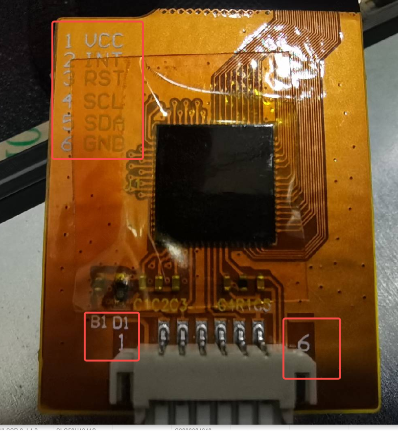
Panel Connector
The supplied cable has different connectors at its ends: 6PIN,MOLEX 53261-0671 (1.25W-TO-B CONN) on the panel side and PH 2mm 1x6P on the other. The adapter therefore needs a PH 2 mm 1×6 connector.
Panel Pinout
The pinout appears on the cable and in FH-101054-V5(6PIN) 全贴合工程图-1028.pdf.
EasyEDA Steps
Open EasyEDA Pro. https://pro.lceda.cn/editor Create a project:
Name the project:
Open the schematic:
Press Shift+F to find these parts: C262262: 6-pin SMD FPC connector, 0.5 mm pitch, horizontal, bottom contact.
C157920: 6-pin PH right-angle connector, 2 mm pitch.
Place the Taishan Pi connector on the left and the touchscreen connector on the right. Connect corresponding signals with net labels.
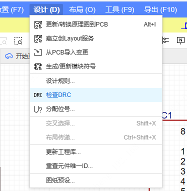
Run DRC and check for errors and warnings.
Update the PCB from the schematic:
Arrange the components. Select a component and press Space to rotate it.
Draw the board outline:
Route the connections indicated by the airwires:
Only GND remains unconnected. Connect it with copper pours.
Draw a copper region the size of the board outline, assign it to GND, and pour the top layer.
Repeat for the bottom layer.
One connection remains because the clearance rules prevent copper from reaching the pin. Route a short trace and add a via; press V while routing to place the via.
Add silkscreen labels for the pinout to help with debugging. Select the silkscreen layer, press T to add text, and adjust its stroke width.
Run DRC again and check for errors and warnings.
Order the PCB and fill in the manufacturing details. Training-camp participants could ask the organizers about PCB coupons.
Order the components:
Consider ordering spare connectors for soldering practice. The author ordered ten.
Place the component order:
The assembled adapter is shown below. See the FPC soldering videos if needed. This adapter connects to Taishan Pi with an opposite-side-contact FPC cable.
Project Files
See Open an EasyEDA Project for import instructions.
Download the adapter project
📌 Find it under 下载中心 → 百度网盘(立创·泰山派开发板资料) → 第09章.【立创·泰山派】项目案例 → 【智能小手机】项目资料 → 6.触摸驱动 → 转接板 → 泰山派10.1寸屏触摸转接板_2024-04-01.epro.
Touch Driver
Driver Files
The Android and Linux SDKs keep touchscreen drivers under SDK/kernel/drivers/input/touchscreen. Start with an existing driver, then use its structure as a reference for your own.
Identify the controller from its marking or the panel documentation. This example uses a Goodix GT9271. The supplier provides GT9xx_Driver_for_Android_V2.4_2014112801.rar, but the SDK already contains a compatible driver. Locate that driver and adapt it to the panel.
The Goodix driver is under SDK/kernel/drivers/input/touchscreen/gt9xx and supports several GT9xx controllers, including GT911, GT910, and GT9271.
Focus on gt9xx.c, gt9xx.h, and Makefile. The .cfg files and gt9xx_cfg.h hold controller configurations; gt9xx_update.c and gt9xx_firmware.h handle firmware updates; goodix_tool.c provides debugging support.
Kernel Configuration
The SDK already enables GT9xx by default. This section explains the configuration process; you can skip it if you only want to use the existing driver. Start with the Makefile under SDK/kernel/drivers/input/touchscreen/gt9xx and trace the parent Makefiles.
#SPDX-License-Identifier: GPL-2.0# 使用 GPL-2.0 许可证声明

#将 goodix_gt9xx.o 目标文件添加到编译选项 obj-y 中
obj-y += goodix_gt9xx.o

#将 gt9xx.o 目标文件添加到 goodix_gt9xx-y 目标列表中,用于编译链接
goodix_gt9xx-y += gt9xx.o

#将 gt9xx_update.o 目标文件也添加到 goodix_gt9xx-y 目标列表中,用于编译链接
goodix_gt9xx-y += gt9xx_update.oSDK/kernel/drivers/input/touchscreen/Makefile
#省略
obj-$(CONFIG_TOUCHSCREEN_GT9XX)     += gt9xx/
#省略CONFIG_TOUCHSCREEN_GT9XX controls whether the driver is built: y builds it into the kernel, m builds a module, and n disables it. Prefer the configuration interface over changing Makefiles directly.
config TOUCHSCREEN_GT9XX
    tristate "Goodix gt9xx support for rockchip platform"
    depends on I2C && ARCH_ROCKCHIP
    help
      Say Y here if you have a touchscreen interface using the gt9xx
      on Rockchip platform, and your board-specific initialization
      code includes that in its table of IIC devices.
If unsure, say N.The Kconfig file alongside the Makefile defines the option shown in menuconfig.
config TOUCHSCREEN_GT9XX
    tristate "Goodix gt9xx support for rockchip platform"
    depends on I2C && ARCH_ROCKCHIP
    help
      Say Y here if you have a touchscreen interface using the gt9xx
      on Rockchip platform, and your board-specific initialization
      code includes that in its table of IIC devices.
If unsure, say N.menuconfig
Run this from the kernel directory:
make ARCH=arm64 menuconfigNavigate through these menus using the arrow keys and Enter:
  │     -> Device Drivers                                                                                                            │
  │       -> Input device support                                                                                                    │
  │         -> Generic input layer (needed for keyboard, mouse, ...) (INPUT [=y])                                                    │
-> Touchscreens (INPUT_TOUCHSCREEN [=y])The driver is already built into the kernel. The keys y, m, and n change the selection.
For demonstration only, the author sets the option to n, then selects Save. Leave your driver enabled; press Esc to exit if you are following along.
Press Enter to confirm:
Return to the menu:
Exit the menus until menuconfig closes.
The build script regenerates .config, so changes saved only there may be overwritten. Generate a defconfig and use it to replace the selected configuration under arch/arm64/configs/.
make ARCH=arm64 savedefconfigThis SDK uses rockchip_linux_defconfig. Replace it with the generated defconfig. Keep a backup if the SDK is not under version control.
mv defconfig arch/arm64/configs/rockchip_linux_defconfigCheck the demonstration change: Delete the existing gt9xx.o and rebuild. With the driver disabled, the build does not regenerate that object.
Build the kernel as described in Build the SDK. In this demonstration, gt9xx.o is no longer generated.
Device Tree Setup
Add the touchscreen configuration to SDK/kernel/arch/arm64/boot/dts/rockchip/tspi-rk3566-dsi-v10.dtsi. This example adapts the supplier's goodix-gt9xx.dtsi reference.
&i2c1 {
    status = "okay";
    ts@5d {
        compatible = "goodix,gt9xx";
        reg = <0x5d>;
        tp-size = <89>;
        max-x = <1280>;
        max-y = <800>;
        touch-gpio = <&gpio1 RK_PA0 IRQ_TYPE_LEVEL_LOW>;
        reset-gpio = <&gpio1 RK_PA1 GPIO_ACTIVE_LOW>;
    };
};I2C1
//i2c1 节点追加
&i2c1 {
    status = "okay";
    /*加触摸*/
};The schematic connects the touchscreen to I²C1, so place its node under i2c1. The board already has pull-up resistors on SDA and SCL.
Touch Node
&i2c1 {
    status = "okay";
    ts@5d { //触摸子节点
        compatible = "goodix,gt9xx"; //这个非常重要,就是靠这个来匹配的驱动
    };
};Corresponding code in gt9xx.c:
static struct of_device_id goodix_ts_dt_ids[] = {
    { .compatible = "goodix,gt9xx" },
    { }
};

static struct i2c_driver goodix_ts_driver = {
    .probe      = goodix_ts_probe,
    .remove     = goodix_ts_remove,
    .id_table   = goodix_ts_id,
    .driver = {
        .name     = GTP_I2C_NAME,
     .of_match_table = of_match_ptr(goodix_ts_dt_ids),
    },
};I²C Address
&i2c1 {
    status = "okay";
    ts@5d { //触摸子节点
        compatible = "goodix,gt9xx";
        reg = <0x5d>; //触摸屏地址
    };
};Several devices can share an I²C bus. Each is selected by its address. Find the touchscreen address in the supplier's reference code or datasheet.
- The supplier's reference code uses
0x5d.
- Check the touchscreen datasheet:
The datasheet lists 0xBA/0xBB, which include the read/write bit. Shift either value right by one bit to get the 7-bit address 0x5D used in the device tree.
Parameters
&i2c1 {
    status = "okay";
    ts@5d {
        compatible = "goodix,gt9xx";
        reg = <0x5d>;
        tp-size = <89>; //触摸大小
        max-x = <1280>; //屏幕最大值
        max-y = <800>;  //屏幕最小值
     };
};The driver reads the touch dimensions and maximum X/Y values from the device tree. Set them for your panel.
    //2649行
    /**************删减***************/
    if (of_property_read_u32(np, "tp-size", &val)) {
        dev_err(&client->dev, "no max-x defined\n");
        return -EINVAL;
    }
    //2715行
    if (of_property_read_u32(np, "max-x", &val)) {
        dev_err(&client->dev, "no max-x defined\n");
        return -EINVAL;
    }
      //2720行
     /**************删减***************/
    //ts->abs_x_max = val;
    if (of_property_read_u32(np, "max-y", &val)) {
        dev_err(&client->dev, "no max-y defined\n");
        return -EINVAL;
    }
/**************删减***************/Interrupt Pin
Polling repeatedly reads the controller even when nothing has changed. With interrupts, the controller signals a touch through INT, and the driver reads the data in response.
Device-tree interrupt configuration:
&i2c1 {
    status = "okay";
    ts@5d {
        compatible = "goodix,gt9xx";
        reg = <0x5d>;
        tp-size = <89>;
        max-x = <1280>;
        max-y = <800>;
        //中断引脚
        touch-gpio = <&gpio1 RK_PA0 IRQ_TYPE_LEVEL_LOW>;
     };
};gt9xx.c reads the touch-gpio property:
//2711行
ts->irq_pin = of_get_named_gpio_flags(np, "touch-gpio", 0, (enum of_gpio_flags *)(&ts->irq_flags));The schematic uses GPIO1_A0 for the interrupt, corresponding to &gpio1 RK_PA0.
This example uses low-level triggering: IRQ_TYPE_LEVEL_LOW.
Reset Pin
&i2c1 {
    status = "okay";
    ts@5d {
        compatible = "goodix,gt9xx";
        reg = <0x5d>;
        tp-size = <89>;
        max-x = <1280>;
        max-y = <800>;
        touch-gpio = <&gpio1 RK_PA0 IRQ_TYPE_LEVEL_LOW>;
        //复位引脚
        reset-gpio = <&gpio1 RK_PA1 GPIO_ACTIVE_LOW>;
    };
};gt9xx.c reads the reset GPIO:
//2712行
ts->rst_pin = of_get_named_gpio_flags(np, "reset-gpio", 0, &rst_flags);The schematic uses GPIO1_A1, corresponding to gpio1 RK_PA1.
GPIO_ACTIVE_LOW specifies an active-low signal.
Test Touch Input
Download the 10.1-inch touchscreen patch
📌 Find it under 下载中心 → 百度网盘(立创·泰山派开发板资料) → 第09章.【立创·泰山派】项目案例 → 【智能小手机】项目资料 → 6.触摸驱动 → 代码补丁 → 泰山派10.1寸触摸补丁.zip.
- Apply the patch using the instructions here:
- Build the kernel and flash the image:
Result
Driver Structure
The GT9xx driver contains many compatibility macros, which can make it hard to follow. We will first write a simulated driver that reports touch events periodically, then adapt it to read the GT9xx controller.
Create a Driver
Create a my_touch directory under SDK/kernel/drivers/input/touchscreen.
kernel/drivers/input/touchscreen$ mkdir my_touch/Change to my_touch:
cd my_touchCreate my_touch.c for the simulated driver:
touch my_touch.cAdd this driver code:
#include <linux/kernel.h>
#include <linux/hrtimer.h>
#include <linux/i2c.h>
#include <linux/input.h>
#include <linux/module.h>
#include <linux/delay.h>
#include <linux/i2c.h>
#include <linux/proc_fs.h>
#include <linux/string.h>
#include <linux/uaccess.h>
#include <linux/vmalloc.h>
#include <linux/interrupt.h>
#include <linux/io.h>
#include <linux/of_gpio.h>
#include <linux/gpio.h>
#include <linux/slab.h>
#include <linux/timer.h>
#include <linux/input/mt.h>
#include <linux/random.h>

#if 1
#define MY_DEBUG(fmt,arg...)  printk("MY_TOUCH:%s %d "fmt"",__FUNCTION__,__LINE__,##arg);
#else
#define MY_DEBUG(fmt,arg...)
#endif
struct input_dev *input_dev;

static struct timer_list my_timer;

void my_timer_callback(struct timer_list *timer)
{
    unsigned int x, y;  // 定义无符号整型变量 x 和 y
    static bool isDown = false;  // 定义静态布尔变量 isDown,并初始化为 false

    // 生成随机数 x,取模得到的值在 [0, 1279] 范围内
    get_random_bytes(&x, sizeof(x));
    x %= 1280;

    // 生成随机数 y,取模得到的值在 [0, 1279] 范围内
    get_random_bytes(&y, sizeof(y));
    y %= 800;

    // 打印调试信息,包括 isDown 的值、x 和 y 的值
    MY_DEBUG("isDown:%d x:%d y:%d!\n", isDown, x, y);

    // 设定输入设备的触摸槽位
    input_mt_slot(input_dev, 0);

    // 报告输入设备的触摸槽位状态,MT_TOOL_FINGER 表示手指状态,isDown 表示是否按下
    input_mt_report_slot_state(input_dev, MT_TOOL_FINGER, isDown);

    // 翻转 isDown 的值模仿手抬起和按下
    isDown = !isDown;

    // 报告输入设备的绝对位置信息:x、y 坐标,触摸面积,触摸宽度
    input_report_abs(input_dev, ABS_MT_POSITION_X, x);
    input_report_abs(input_dev, ABS_MT_POSITION_Y, y);

    // 报告输入设备的指针仿真信息
    input_mt_report_pointer_emulation(input_dev, true);

    // 同步输入事件
    input_sync(input_dev);

    // 重新设置定时器,2 秒后再次触发
    mod_timer(timer, jiffies + msecs_to_jiffies(200));
}

static int my_touch_ts_probe(struct i2c_client *client,
            const struct i2c_device_id *id)
{
    int ret;

    // 打印调试信息
    MY_DEBUG("locat");

    // 分配输入设备对象
    input_dev = devm_input_allocate_device(&client->dev);
    if (!input_dev) {
        dev_err(&client->dev, "Failed to allocate input device.\n");
        return -ENOMEM;
    }

    // 设置输入设备的名称和总线类型
    input_dev->name = "my touch screen";
    input_dev->id.bustype = BUS_I2C;

    /*设置触摸 x 和 y 的最大值*/
    // 设置输入设备的绝对位置参数
    input_set_abs_params(input_dev, ABS_MT_POSITION_X, 0, 1280, 0, 0);
    input_set_abs_params(input_dev, ABS_MT_POSITION_Y, 0, 800, 0, 0);

    // 初始化多点触摸设备的槽位
    ret = input_mt_init_slots(input_dev, 5, INPUT_MT_DIRECT);
    if (ret) {
        dev_err(&client->dev, "Input mt init error\n");
        return ret;
    }

    // 注册输入设备
    ret = input_register_device(input_dev);
    if (ret)
        return ret;

    // 初始化定时器
    timer_setup(&my_timer, my_timer_callback, 0);

    // 设置定时器,5 秒后第一次触发
    mod_timer(&my_timer, jiffies + msecs_to_jiffies(5000));

    return 0;
}

static int my_touch_ts_remove(struct i2c_client *client)
{
    MY_DEBUG("locat");
    return 0;
}

static const struct of_device_id my_touch_of_match[] = {
    { .compatible = "my,touch", },
    { /* sentinel */ }
};
MODULE_DEVICE_TABLE(of, my_touch_of_match);

static struct i2c_driver my_touch_ts_driver = {
    .probe      = my_touch_ts_probe,
    .remove     = my_touch_ts_remove,
    .driver = {
        .name     = "my-touch",
     .of_match_table = of_match_ptr(my_touch_of_match),
    },
};

static int __init my_ts_init(void)
{
    MY_DEBUG("locat");
    return i2c_add_driver(&my_touch_ts_driver);
}

static void __exit my_ts_exit(void)
{
    MY_DEBUG("locat");
    i2c_del_driver(&my_touch_ts_driver);
}

module_init(my_ts_init);
module_exit(my_ts_exit);

MODULE_LICENSE("GPL");
MODULE_DESCRIPTION("My touch driver");
MODULE_AUTHOR("wucaicheng@qq.com");Create a Makefile to build my_touch.c:
#如果编译成.ko的话就选obj-m,如果编译到内核就obj-y
obj-y += my_touch.oAdd my_touch to the parent touchscreen/Makefile:
#obj-n 把gt9xx给屏蔽掉避免后面影响
obj-n                               += gt9xx/
#obj-y 编译我们的my_touch
obj-y += my_touch/Add the simulated device under &i2c1 in SDK/kernel/arch/arm64/boot/dts/rockchip/tspi-rk3566-dsi-v10.dtsi:
    myts@5d {
        compatible = "my,touch";
        reg = <0x5d>;
        tp-size = <89>;
        max-x = <1280>;
        max-y = <800>;
        touch-gpio = <&gpio1 RK_PA0 IRQ_TYPE_LEVEL_LOW>;
        reset-gpio = <&gpio1 RK_PA1 GPIO_ACTIVE_HIGH>;
};Patch
Download the code patch
📌 Find it under 下载中心 → 百度网盘(立创·泰山派开发板资料) → 第09章.【立创·泰山派】项目案例 → 【智能小手机】项目资料 → 6.触摸驱动 → 代码补丁 → my_touch_patch.zip.
Test the Driver
Build into the Kernel
The example Makefile uses obj-y, so the driver is built into the kernel. Rebuild and flash the kernel using the earlier instructions.
Build a Module
To load the driver separately, change obj-y to obj-m in the my_touch Makefile. Build a .ko module and transfer it to Taishan Pi.
#如果编译成.ko的话就选obj-m,如果编译到内核就obj-y
obj-m += my_touch.oA successful module build generates my_touch.ko:
kernel$ make ARCH=arm64 -C . M=./drivers/input/touchscreen/my_touchmakeruns the kernel build system.ARCH=arm64selects the 64-bit ARM target.-C .uses the current directory as the kernel source directory.M=./drivers/input/touchscreen/my_touch/specifies the module directory.
Load the Module
Use ADB to push my_touch.ko to Taishan Pi:
adb root && adb remount && adb push Z:\tspi\Android11_20231007\PublicVersion\kernel\drivers\input\touchscreen\my_touch\my_touch.ko /vendor/lib/modulesadb rootrequests root access on the Android device.adb remountremounts the filesystem so the module directory can be written.adb push <local-path> <device-path>copies the module to/vendor/lib/modules. Replace the example Windows path with the location of your builtmy_touch.ko.
Open an ADB shell:
Load the driver:
rk3566_tspi:/ # insmod /vendor/lib/modules/my_touch.koCheck whether it loaded:
rk3566_tspi:/ # lsmod
Module                  Size  Used by
my_touch               16384  0
bcmdhd 1175552 0The log shows the simulated driver reporting data:
Result
The display receives simulated touch points:
Driver structure:
The first driver reports simulated touch points without a connected touchscreen. The simplified version below keeps only the basic structure and adds log messages to show the execution order.
/*
 * 有些同学会好奇我怎么知道包含哪些头文件,其实我也不是一个个去找到的,
 * 我直接把gt9xx那里复制过来的,后面缺少什么就在加什么
 * 这里是驱动所依赖的头文件,它们提供了驱动编写所需的各种函数和宏定义。
 */
#include <linux/kernel.h>       // 内核常用宏和函数
#include <linux/hrtimer.h>      // 高精度定时器
#include <linux/i2c.h>          // I2C总线支持
#include <linux/input.h>        // 输入设备支持
#include <linux/module.h>       // 模块支持
#include <linux/delay.h>        // 延时函数
#include <linux/proc_fs.h>      // /proc文件系统支持
#include <linux/string.h>       // 字符串操作
#include <linux/uaccess.h>      // 用户空间访问支持
#include <linux/vmalloc.h>      // 虚拟内存分配
#include <linux/interrupt.h>    // 中断处理
#include <linux/io.h>           // IO操作
#include <linux/of_gpio.h>      // Open Firmware GPIO支持
#include <linux/gpio.h>         // GPIO操作
#include <linux/slab.h>         // 内存分配(如kmalloc和kfree)

/*
 * 这里我简单的封装了一个打印函数,回打印对应的函数和行号,方便定位消息
 * MY_DEBUG宏用于调试,当#if 1为真时,它将使用printk打印调试信息,包括函数名和行号。
 */
#if 1
#define MY_DEBUG(fmt,arg...)  printk("MY_TOUCH:%s %d "fmt"",__FUNCTION__,__LINE__,##arg);
#else
#define MY_DEBUG(fmt,arg...)  // 当#if 0时,MY_DEBUG不执行任何操作
#endif

/*
 * 探针函数
 * 这是I2C驱动的核心函数之一,当I2C总线上有新的设备被识别时,这个函数会被调用。
 */
static int my_touch_ts_probe(struct i2c_client *client,
            const struct i2c_device_id *id)
{
    MY_DEBUG("probe");  // 打印调试信息
    return 0;           // 返回0表示成功
}

/*
 * 移除函数
 * 当I2C设备从总线上移除时,这个函数会被调用。
 */
static int my_touch_ts_remove(struct i2c_client *client)
{
    MY_DEBUG("remove"); // 打印调试信息
    return 0;           // 返回0表示成功
}

/*
 * 设备匹配表
 * 用于匹配设备树中的设备节点。
 */
static const struct of_device_id my_touch_of_match[] = {
    { .compatible = "my,touch", },  // 兼容的设备树节点名称
    { /* sentinel */ }              // 列表结束标志
};
MODULE_DEVICE_TABLE(of, my_touch_of_match); // 注册设备匹配表

/*
 * I2C驱动结构体
 * 定义了I2C驱动的基本信息。
 */
static struct i2c_driver my_touch_ts_driver = {
    .probe      = my_touch_ts_probe,   // 探针函数  ,用于探测和初始化I2C设备
    .remove     = my_touch_ts_remove,  // 移除函数 ,用于清理和卸载I2C设备
    .driver = {
        .name     = "my-touch",         // 驱动名称
        .of_match_table = of_match_ptr(my_touch_of_match), // 设备树匹配表
    },
};

/*
 * 模块初始化函数
 * 当模块加载时,这个函数会被调用。
 */
static int __init my_ts_init(void)
{
    MY_DEBUG("init"); // 打印调试信息
    return i2c_add_driver(&my_touch_ts_driver); // 注册I2C驱动
}

/*
 * 模块退出函数
 * 当模块卸载时,这个函数会被调用。
 */
static void __exit my_ts_exit(void)
{
    MY_DEBUG("exit"); // 打印调试信息
    i2c_del_driver(&my_touch_ts_driver); // 注销I2C驱动
}

/*
 * 使用module_init和module_exit宏来指定模块的初始化和退出函数。
 * 当模块被加载时,my_ts_init函数会被调用;当模块被卸载时,my_ts_exit函数会被调用。
 */
module_init(my_ts_init);     // 模块初始化时调用my_ts_init函数
module_exit(my_ts_exit);     // 模块退出时调用my_ts_exit函数

/*
 * 模块的许可证、描述和作者信息
 * 这些信息会被内核用来标识和管理模块。
 */
MODULE_LICENSE("GPL");       // 模块使用GNU通用公共许可证
MODULE_DESCRIPTION("My touch driver");  // 模块描述
MODULE_AUTHOR("wucaicheng@qq.com"); // 模块作者Driver loading sequence:
module_init(my_ts_init);
    my_ts_init
        i2c_del_driver(&my_touch_ts_driver); // 注销I2C驱动
            static const struct of_device_id my_touch_of_match[] = {
                { .compatible = "my,touch", },  // 兼容的设备树节点名称
                { /* sentinel */ }              // 列表结束标志
            };
            static struct i2c_driver my_touch_ts_driver = {
                .probe      = my_touch_ts_probe,
                .remove     = my_touch_ts_remove,
                .driver = {
                    // 驱动名称,加载后在/sys/bus/i2c/drivers/下可见为my-touch
                    .name     = "my-touch",
                 .of_match_table = of_match_ptr(my_touch_of_match),
                },
            };
my_touch_ts_probe //当"my,touch"和设备树中匹配成功以后就执行此函数Build and load the driver using the previous steps. The log shows which functions run during loading.
Driver unloading sequence:
module_exit(my_ts_exit);
    my_ts_exit
my_touch_ts_removeUnload the driver and inspect the log to see the removal functions.
Many drivers follow this structure. An I²C driver registers through i2c_add_driver; drivers for other buses use their corresponding registration functions.
Input Setup
The input subsystem lets the driver allocate an input device, configure its capabilities, and report events. The following sections walk through these steps.
Allocate an Input Device
Call devm_input_allocate_device to allocate an input device:
    input_dev = devm_input_allocate_device(&client->dev);
    if (!input_dev) {
        dev_err(&client->dev, "Failed to allocate input device.\n");
        return -ENOMEM;
}Set the Name and Device Type
Assign a name and specify the device type:
    input_dev->name = "my touch screen";
input_dev->id.bustype = BUS_I2C;On Taishan Pi, use cat /proc/bus/input/devices or Android's getevent to find my touch screen.
Set Coordinate Ranges
Set the minimum and maximum X/Y coordinates to match the display. Incorrect ranges can make touches map to only a small part of the screen.
    input_set_abs_params(input_dev, ABS_MT_POSITION_X, 0, 1280, 0, 0);
input_set_abs_params(input_dev, ABS_MT_POSITION_Y, 0, 800, 0, 0);input_dev: Pointer to the input device being configured.axis: The axis to configure;ABS_MT_POSITION_Xselects the X coordinate.min: Minimum value, 0 in this example.max: Maximum value, 1280 in this example.fuzz: Noise-filtering tolerance, 0 here.flat: Dead-zone setting, 0 here.
Initialize Multitouch
GT9xx controllers support multiple simultaneous touches. Call input_mt_init_slots to initialize multitouch slots.
    ret = input_mt_init_slots(input_dev, 5, INPUT_MT_DIRECT);
    if (ret) {
        dev_err(&client->dev, "Input mt init error\n");
        return ret;
}input_dev: Pointer to the input device.num_slots: Number of slots, 5 here.flags:INPUT_MT_DIRECTidentifies a direct-touch device;INPUT_MT_POINTERidentifies a pointer device.
Register the Input Device
Register the configured input device:
    ret = input_register_device(input_dev);
    if (ret)
return ret;Unregister the Input Device
The earlier example omits cleanup. Add the unregister operation shown below; without it, unloading with rmmod can crash the system.
static int my_touch_ts_remove(struct i2c_client *client)
{
    MY_DEBUG("locat");
    input_unregister_device(input_dev);
    return 0;
}Report Events
Select a Slot
For multitouch input, select the slot whose data you are reporting. GT9271 supports up to ten simultaneous touch points.
input_mt_slot(input_dev, 0);Report Touch State
Report whether the touch is active or released:
//按下
input_mt_report_slot_state(input_dev, MT_TOOL_FINGER, true);
//松开
input_mt_report_slot_state(input_dev, MT_TOOL_FINGER, false);input_dev: Pointer to the input device.tool_type:MT_TOOL_FINGERidentifies a finger.active:truefor an active touch,falsefor release.
Report Coordinates
For an active touch, report its coordinates:
    input_report_abs(input_dev, ABS_MT_POSITION_X, x);
input_report_abs(input_dev, ABS_MT_POSITION_Y, y);Pointer Emulation
This converts multitouch events into pointer events.
input_mt_report_pointer_emulation(input_dev, true);Synchronize Events
Call input_sync after reporting a set of events with functions such as input_report_abs and input_mt_report_slot_state. It completes the event frame for the input subsystem.
input_sync(input_dev);Timer
Initialize
Without a physical touchscreen, use a timer to simulate touch events.
//定时器回调函数
void my_timer_callback(struct timer_list *timer){
    //为了实现重复
    mod_timer(timer, jiffies + msecs_to_jiffies(200));
} // 初始化定时器
timer_setup(&my_timer, my_timer_callback, 0);This schedules the timer callback five seconds later:
    // 设置定时器,5 秒后第一次触发
mod_timer(&my_timer, jiffies + msecs_to_jiffies(5000));Delete
del_timer_sync(&my_timer);Read Touch Input
#include "linux/stddef.h"
#include <linux/kernel.h>
#include <linux/hrtimer.h>
#include <linux/i2c.h>
#include <linux/input.h>
#include <linux/module.h>
#include <linux/delay.h>
#include <linux/i2c.h>
#include <linux/proc_fs.h>
#include <linux/string.h>
#include <linux/uaccess.h>
#include <linux/vmalloc.h>
#include <linux/interrupt.h>
#include <linux/io.h>
#include <linux/of_gpio.h>
#include <linux/gpio.h>
#include <linux/slab.h>
#include <linux/timer.h>
#include <linux/input/mt.h>
#include <linux/random.h>

#define MY_SWAP(x, y)                 do{\
                                         typeof(x) z = x;\
                                         x = y;\
                                         y = z;\
                                       }while (0)

#if 1
#define MY_DEBUG(fmt,arg...)  printk("MY_TOUCH:%s %d "fmt"",__FUNCTION__,__LINE__,##arg);
#else
#define MY_DEBUG(fmt,arg...)
#endif

struct my_touch_dev {
    struct i2c_client *client;
    struct input_dev *input_dev;
    int rst_pin;
    int irq_pin;
    u32 abs_x_max;
    u32 abs_y_max;
    int irq;
};

s32 my_touch_i2c_read(struct i2c_client *client,u8 *addr,u8 addr_len, u8 *buf, s32 len)
{
    struct i2c_msg msgs[2];
    s32 ret=-1;
    msgs[0].flags = !I2C_M_RD;
    msgs[0].addr  = client->addr;
    msgs[0].len   = addr_len;
    msgs[0].buf   = &addr[0];
    msgs[1].flags = I2C_M_RD;
    msgs[1].addr  = client->addr;
    msgs[1].len   = len;
    msgs[1].buf   = &buf[0];

    ret = i2c_transfer(client->adapter, msgs, 2);
    if(ret == 2)return 0;

    if(addr_len == 2){
        MY_DEBUG("I2C Read: 0x%04X, %d bytes failed, errcode: %d! Process reset.", (((u16)(addr[0] << 8)) | addr[1]), len, ret);
    }else {
        MY_DEBUG("I2C Read: 0x%02X, %d bytes failed, errcode: %d! Process reset.", addr[0], len, ret);
    }

    return -1;
}

s32 my_touch_i2c_write(struct i2c_client *client, u8 *addr, u8 addr_len, u8 *buf,s32 len)
{
    struct i2c_msg msg;
    s32 ret = -1;
    u8 *temp_buf;

    msg.flags = !I2C_M_RD;
    msg.addr  = client->addr;
    msg.len   = len+addr_len;

    temp_buf= kzalloc(msg.len, GFP_KERNEL);
    if (!temp_buf){
        goto error;
    }

    // 装填地址
    memcpy(temp_buf, addr, addr_len);
    // 装填数据
    memcpy(temp_buf + addr_len, buf, len);
    msg.buf = temp_buf;

    ret = i2c_transfer(client->adapter, &msg, 1);
    if (ret == 1) {
        kfree(temp_buf);
        return 0;
    }

error:
    if(addr_len == 2){
        MY_DEBUG("I2C Read: 0x%04X, %d bytes failed, errcode: %d! Process reset.", (((u16)(addr[0] << 8)) | addr[1]), len, ret);
    }else {
        MY_DEBUG("I2C Read: 0x%02X, %d bytes failed, errcode: %d! Process reset.", addr[0], len, ret);
    }
    if (temp_buf)
        kfree(temp_buf);
    return -1;
}

static irqreturn_t my_touch_irq_handler(int irq, void *dev_id)
{
    s32 ret = -1;
    struct my_touch_dev *ts = dev_id;
    u8 addr[2] = {0x81,0x4E};
    u8 clear_buf[1] = {0};
    u8 point_data[1+8*1]={0};//1个状态位置+10个触摸点,一个点是8个数据组成
    u8 touch_num = 0;
    u8 buf_stats = 0;
    u8 *coor_data;
    int id,input_x,input_y,input_w;

    MY_DEBUG("irq");

    ret = my_touch_i2c_read(ts->client, addr,sizeof(addr), point_data, sizeof(point_data));
    if (ret < 0){
        MY_DEBUG("I2C write end_cmd error!");
    }

    touch_num = point_data[0]&0x0f;
    buf_stats = point_data[0]&0x80>>7;

    MY_DEBUG("0x814E=:%0x,touch_num:%d,buf_stats:%d",point_data[0],touch_num,buf_stats);
    //获取
    if (touch_num){
        coor_data = &point_data[1];

        id = coor_data[0] & 0x0F;
        input_x  = coor_data[1] | (coor_data[2] << 8);
        input_y  = coor_data[3] | (coor_data[4] << 8);
        input_w  = coor_data[5] | (coor_data[6] << 8);
        MY_DEBUG("id:%d,x:%d,y:%d,w:%d",id,input_x,input_y,input_w);
        //     // 设定输入设备的触摸槽位
        input_mt_slot(ts->input_dev, 0);

        // 报告输入设备的触摸槽位状态,MT_TOOL_FINGER 表示手指状态,isDown 表示是否按下
        input_mt_report_slot_state(ts->input_dev, MT_TOOL_FINGER, true);

        // 翻转 isDown 的值模仿手抬起和按下
        MY_SWAP(input_x, input_y);
        // 报告输入设备的绝对位置信息:x、y 坐标,触摸面积,触摸宽度
        input_report_abs(ts->input_dev, ABS_MT_POSITION_X, 800-input_x);
        input_report_abs(ts->input_dev, ABS_MT_POSITION_Y, input_y);

    }else {
        input_mt_report_slot_state(ts->input_dev, MT_TOOL_FINGER, false);
    }

    // 清除寄存器,要不然回反复触发
    ret = my_touch_i2c_write(ts->client,  addr,sizeof(addr), clear_buf, sizeof(clear_buf));
    if (ret < 0){
        MY_DEBUG("I2C write end_cmd error!");
    }

    // 报告输入设备的指针仿真信息
    input_mt_report_pointer_emulation(ts->input_dev, true);

    // 同步输入事件
    input_sync(ts->input_dev);

    return IRQ_HANDLED;
}

s32 gt9271_read_version(struct i2c_client *client)
{
    s32 ret = -1;
    u8 addr[2] = {0x81,0x40};
    u8 buf[6] = {0};

    ret = my_touch_i2c_read(client, addr,sizeof(addr), buf, sizeof(buf));
    if (ret < 0){
        MY_DEBUG("GTP read version failed");
        return ret;
    }

    if (buf[5] == 0x00){
        MY_DEBUG("IC Version: %c%c%c_%02x%02x", buf[0], buf[1], buf[2], buf[5], buf[4]);
    }
    else{
        MY_DEBUG("IC Version: %c%c%c%c_%02x%02x", buf[0], buf[1], buf[2], buf[3], buf[5], buf[4]);
    }
    return ret;
}

static int my_touch_ts_probe(struct i2c_client *client,
            const struct i2c_device_id *id)
{
    int ret;
    struct my_touch_dev *ts;
    struct device_node *np = client->dev.of_node;
    // 打印调试信息
    MY_DEBUG("locat");

    // ts = kzalloc(sizeof(*ts), GFP_KERNEL);
    ts = devm_kzalloc(&client->dev, sizeof(*ts), GFP_KERNEL);
    if (ts == NULL){
        dev_err(&client->dev, "Alloc GFP_KERNEL memory failed.");
        return -ENOMEM;
    }
    ts->client = client;
    i2c_set_clientdata(client, ts);

    if (of_property_read_u32(np, "max-x", &ts->abs_x_max)) {
        dev_err(&client->dev, "no max-x defined\n");
        return -EINVAL;
    }
    MY_DEBUG("abs_x_max:%d",ts->abs_x_max);

    if (of_property_read_u32(np, "max-y", &ts->abs_y_max)) {
        dev_err(&client->dev, "no max-y defined\n");
        return -EINVAL;
    }
    MY_DEBUG("abs_x_max:%d",ts->abs_y_max);

    //找复位gpio
    ts->rst_pin = of_get_named_gpio(np, "reset-gpio", 0);
    //申请复位gpio
    ret = devm_gpio_request(&client->dev,ts->rst_pin,"my touch touch gpio");
    if (ret < 0){
        dev_err(&client->dev, "gpio request failed.");
        return -ENOMEM;
    }

    //找中断引进
    ts->irq_pin = of_get_named_gpio(np, "touch-gpio", 0);
    /* 申请使用管脚 */
    ret = devm_gpio_request_one(&client->dev, ts->irq_pin,
                GPIOF_IN, "my touch touch gpio");
    if (ret < 0)
        return ret;

    gpio_direction_output(ts->rst_pin,0);
    msleep(20);
    gpio_direction_output(ts->irq_pin,0);
    msleep(2);
    gpio_direction_output(ts->rst_pin,1);
    msleep(6);
    gpio_direction_output(ts->irq_pin, 0);
    gpio_direction_output(ts->irq_pin, 0);
    msleep(50);

    //申请中断
    ts->irq = gpio_to_irq(ts->irq_pin);
    if(ts->irq){
        ret = devm_request_threaded_irq(&(client->dev), ts->irq, NULL,
            my_touch_irq_handler, IRQF_TRIGGER_FALLING | IRQF_ONESHOT ,
            client->name, ts);
        if (ret != 0) {
            MY_DEBUG("Cannot allocate ts INT!ERRNO:%d\n", ret);
            return ret;
        }
    }

    // 分配输入设备对象
    ts->input_dev = devm_input_allocate_device(&client->dev);
    if (!ts->input_dev) {
        dev_err(&client->dev, "Failed to allocate input device.\n");
        return -ENOMEM;
    }

    // 设置输入设备的名称和总线类型
    ts->input_dev->name = "my touch screen";
    ts->input_dev->id.bustype = BUS_I2C;

    /*设置触摸 x 和 y 的最大值*/
    // 设置输入设备的绝对位置参数
    input_set_abs_params(ts->input_dev, ABS_MT_POSITION_X, 0, 800, 0, 0);
    input_set_abs_params(ts->input_dev, ABS_MT_POSITION_Y, 0, 1280, 0, 0);

    // 初始化多点触摸设备的槽位
    ret = input_mt_init_slots(ts->input_dev, 5, INPUT_MT_DIRECT);
    if (ret) {
        dev_err(&client->dev, "Input mt init error\n");
        return ret;
    }

    // 注册输入设备
    ret = input_register_device(ts->input_dev);
    if (ret)
        return ret;

    gt9271_read_version(client);


    return 0;
}

static int my_touch_ts_remove(struct i2c_client *client)
{
    struct my_touch_dev *ts = i2c_get_clientdata(client);
    MY_DEBUG("locat");
    input_unregister_device(ts->input_dev);
    return 0;
}

static const struct of_device_id my_touch_of_match[] = {
    { .compatible = "my,touch", },
    { /* sentinel */ }
};
MODULE_DEVICE_TABLE(of, my_touch_of_match);

static struct i2c_driver my_touch_ts_driver = {
    .probe      = my_touch_ts_probe,
    .remove     = my_touch_ts_remove,
    .driver = {
        .name     = "my-touch",
     .of_match_table = of_match_ptr(my_touch_of_match),
    },
};

static int __init my_ts_init(void)
{
    MY_DEBUG("locat");
    return i2c_add_driver(&my_touch_ts_driver);
}

static void __exit my_ts_exit(void)
{
    MY_DEBUG("locat");
    i2c_del_driver(&my_touch_ts_driver);
}

module_init(my_ts_init);
module_exit(my_ts_exit);

MODULE_LICENSE("GPL");
MODULE_DESCRIPTION("My touch driver");
MODULE_AUTHOR("wucaicheng@qq.com");Patch:
Download my_touch_gt9271.zip
📌 Find it under 下载中心 → 百度网盘(立创·泰山派开发板资料) → 第09章.【立创·泰山派】项目案例 → 【智能小手机】项目资料 → 6.触摸驱动 → 代码补丁 → my_touch_gt9271.zip.
Exercises
- [ ] Extend the single-touch example to support multitouch.
- [ ] Adapt the driver to your own touchscreen if it differs from this example.
Debugging
Logic Analyzer
i2c-tool
i2cdetect
i2cdetect -y 1
     0  1  2  3  4  5  6  7  8  9  a  b  c  d  e  f
00:          -- -- -- -- -- -- -- -- -- -- -- -- --
10: -- -- -- -- -- -- -- -- -- -- -- -- -- -- -- --
20: -- -- -- -- -- -- -- -- -- -- -- -- -- -- -- --
30: -- -- -- -- -- -- -- -- -- -- -- -- -- -- -- --
40: -- -- -- -- -- -- -- -- -- -- -- -- -- -- -- --
50: -- -- -- -- -- -- -- -- -- -- -- -- -- UU -- --
60: -- -- -- -- -- -- -- -- -- -- -- -- -- -- -- --
70: -- -- -- -- -- -- -- --getevent
#getevent
add device 1: /dev/input/event7
  name:     "my touch screen"
add device 2: /dev/input/event0
  name:     "fe700030.pwm"
add device 3: /dev/input/event5
  name:     "SEM USB Keyboard System Control"
add device 4: /dev/input/event3
  name:     "SEM USB Keyboard"
add device 5: /dev/input/event2
  name:     "adc-keys"
add device 6: /dev/input/event4
  name:     "SEM USB Keyboard Consumer Control"
add device 7: /dev/input/event6
  name:     " USB OPTICAL MOUSE"
add device 8: /dev/input/event1
  name:     "rk805 pwrkey"
/dev/input/event7: 0003 0039 00000017
/dev/input/event7: 0003 0035 00000220
/dev/input/event7: 0003 0036 00000275
/dev/input/event7: 0001 014a 00000001
/dev/input/event7: 0003 0000 00000220
/dev/input/event7: 0003 0001 00000275
/dev/input/event7: 0000 0000 00000000