6. External Interrupt
6.1 What Is an Interrupt?
In the world of microprocessors and microcontrollers, an interrupt is a special event that interrupts and temporarily suspends the currently running program so a specific condition or event can be handled. Examples include pressing a button, reaching a timer period, or receiving serial port data. An interrupt is an important computer system concept that responds to these specific situations asynchronously. Here is an example: suppose we are writing code and suddenly a phone call comes in. We stop writing code, answer the call, and then continue writing code after the call is finished. The phone call is equivalent to an interrupt: it interrupts what we are currently doing. Answering the call is equivalent to the operation that the interrupt needs to execute, also called the interrupt service routine.
Interrupts can be divided into hardware interrupts and software interrupts.
Hardware interrupts are usually triggered by physical events from external devices, such as pressing a button, a timer reaching its target time, or data arriving at a serial port. When these events occur, the microprocessor immediately pauses its current task and jumps to a predefined interrupt service routine, ISR, to respond to the event.
Software interrupts are triggered by software instructions and are usually used for more complex processing tasks. Operating system system calls often use software interrupts.
6.2 External Interrupt Introduction
In the previous chapter, when performing the button experiment, we could read GPIO input, but the code continuously checked for changes on the IO input pin. If a large amount of code is added later, it may take a long time before the polling reaches the button detection section, so the efficiency is low. This is especially wasteful in some scenarios, such as a button that may only be pressed once a day to execute a related function. To solve this problem, we introduce the concept of external interrupts. As the name suggests, the related function is executed only when the button is pressed, or when an interrupt is generated. This greatly saves CPU resources, so interrupts are widely used in real projects.
An external interrupt is a type of hardware interrupt triggered by an event outside the microcontroller. Some microcontroller pins are designed to respond to specific events, such as button presses or sensor signal changes. These specified pins are usually called external interrupt pins.
When an external interrupt event occurs, the currently executing program stops immediately and jumps to the corresponding interrupt service routine, ISR, for processing. After processing is complete, the program returns to the interrupted point and continues execution.
For embedded systems and real-time systems, using external interrupts is very important. They help the system respond to external events immediately, greatly improving system efficiency and real-time performance. The ESP32S3 development board provides many pins that can be used as external interrupt pins. These pins can be configured for external interrupt experiments.
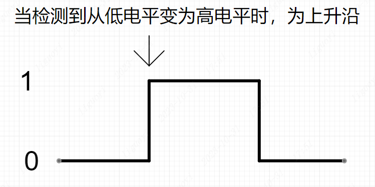
ESP32S3 external interrupts support rising-edge trigger, falling-edge trigger, low-level trigger, and high-level trigger modes. Rising-edge and falling-edge triggers are shown below:
After a pin is configured as an external interrupt pin, when the configured trigger mode is detected on the pin, the program enters the interrupt callback function and executes the corresponding code.
6.3 Functions and Advantages of External Interrupts
The external interrupt function of ESP32S3 has the following functions and advantages in Arduino development:
- Real-time response to external events: ESP32S3 external interrupts allow Arduino to respond immediately when an external event is detected. These external events may come from sensors, buttons, switches, received signals, and so on. With external interrupts, these events can be captured in real time and the corresponding operations can be executed without frequent polling or waiting.
- Saving computing resources: external interrupts allow the task of handling external events to be transferred to chip hardware, saving processor computing resources. Compared with software polling, external interrupts reduce processor load and allow other resources to be used more effectively for more complex tasks.
- Accurate event capture: ESP32S3 external interrupts can capture external event triggers very accurately. You can configure the interrupt trigger mode, such as rising edge, falling edge, any level change, low-level hold, high-level hold, and so on, to adapt to different external events. When the event occurs, current program execution is interrupted immediately and the interrupt service routine, ISR, is executed.
- High-priority processing: external interrupts can be configured for high-priority processing, taking priority over the currently running program. This is useful for important events that require immediate response, such as emergency notifications or sensor detection. When an external event is triggered, the processor immediately switches to the interrupt service routine to process the operation promptly and accurately, avoiding processing delays.
- Multiple interrupt handling: ESP32S3 supports multiple external interrupts. You can connect multiple external events to different interrupt pins to process multiple events in parallel. This allows one Arduino to process multiple sensors, switches, and other external events, improving system flexibility and scalability.
In short, ESP32S3 external interrupts provide Arduino projects with advantages such as real-time response, computing resource savings, accurate event capture, high-priority processing, and multiple interrupt handling. They provide a more flexible and efficient way to process external events and help build more powerful and reliable applications.
6.4 External Interrupt Usage Flow
The typical flow for using an external interrupt is as follows:
Configure the Pin
Because an external interrupt still reads the pin state, the pin must be set as input or pull-up input mode. In the setup() function, use pinMode() to configure the pin as an input pin.
For details about the
pinMode()function, see the LED chapter.
int interruptPin = 0; // Interrupt pin GPIO0
void setup() {
// Set GPIO0 as input mode
pinMode(interruptPin, INPUT);
}Bind the Pin to the Interrupt Service Routine and Set the Trigger Mode
In the setup() function, use attachInterrupt() to bind the interrupt service routine to the pin. You can choose the interrupt trigger mode, such as rising edge, falling edge, or state change:
int interruptPin = 0;
void setup() {
// Other code omitted...
// Configure GPIO0 as the interrupt pin. The external interrupt callback is ISR(), triggered on falling edge.
attachInterrupt(digitalPinToInterrupt(interruptPin), ISR, FALLING);
}The attachInterrupt() function is part of the Arduino API. It binds a function, the interrupt service routine ISR, to an external interrupt pin. When the external interrupt pin meets the specified condition, such as a pin level change, the corresponding interrupt service routine is automatically called. This function is most commonly used for real-time operations and interrupt events. The function prototype is:
attachInterrupt(digitalPinToInterrupt(pin), ISR, mode);Here, pin is the GPIO pin number to configure as an interrupt pin. ISR is the function name or pointer of the interrupt service routine to bind. mode is the interrupt trigger condition, meaning the condition that triggers the interrupt. Common trigger conditions include rising edge, falling edge, and state change. Related parameters are:
CHANGE: the trigger condition is a pin level change, meaning either low-to-high or high-to-low changes will trigger an interrupt.RISING: the trigger condition is when the pin changes from low level to high level.FALLING: the trigger condition is when the pin changes from high level to low level.LOW: the trigger condition is when the pin remains at low level.HIGH: the trigger condition is when the pin remains at high level.
Note that attachInterrupt() only applies to GPIO pins supported by digitalPinToInterrupt(). Not all GPIO pins can be used for external interrupts. In addition, when performing interrupt processing inside the interrupt service function, avoid operations that consume a large amount of CPU time, such as delay functions, to ensure interrupt response speed and accuracy.
attachInterrupt() has two ways to pass the function: a function pointer or a function name. If passing a function name, pass the function name directly without parentheses. If parentheses are added after the function name, the function is called and its return value is passed. If using a function pointer, add the & symbol before the function name.
The following is an example of attachInterrupt():
void button_ISR() {
// Handle the button interrupt event
}

void setup() {
// Configure GPIO 5 as an input pin
pinMode(5, INPUT);
// Bind the button connected to GPIO5 to the interrupt service routine button_ISR, triggered on rising edge
attachInterrupt(digitalPinToInterrupt(5), button_ISR, RISING);
}

void loop() {
// Handle other tasks in the main loop
} In this example, GPIO5 is configured as an input pin, and the button connected to GPIO5 is bound to the rising-edge-triggered interrupt service routine. When the button is pressed, the button pin becomes high. The level change on the button pin triggers a rising-edge interrupt, and the interrupt service routine button_ISR() is executed.
Handle Interrupt Events
The following notes use the interrupt callback function button_ISR() from the example above. When using interrupts in Arduino, pay attention to the following:
a. Keep the interrupt routine as short as possible.
b. Avoid using blocking functions, such as delay(), in interrupt handlers. Use non-blocking delay methods, such as the micros() function, for operations that require delay so interrupts can execute normally and the system remains stable. This is because delay() blocks the whole system, including normal interrupt execution. When an interrupt is triggered, the handler should finish as quickly as possible to ensure timely response and avoid interrupt backlog.
c. Variables shared with the main program should be declared with the volatile keyword.
d. When using interrupts in Arduino, avoid using Serial print functions in interrupt handlers. Using Serial print functions inside an interrupt handler can cause the following problems:
- Time delay:
Serialprint functions are usually time-consuming operations. They block interrupt execution time and delay interrupt response. This may cause other important interrupt events to be missed during the interrupt or may make the system unstable. - Buffer overflow: the
Serialobject uses an internal buffer to store data to be sent. IfSerialprint functions are called frequently inside an interrupt handler, the buffer may overflow, causing data loss or unpredictable behavior.
To avoid these problems, it is recommended to avoid using Serial print functions in interrupt handlers. If debugging information must be output from an interrupt handler, use another method such as setting a flag and checking the flag in the main loop before printing.
❓What is volatile?
volatile is a keyword used to tell the compiler that the declared variable may be changed by factors outside the normal program flow. Its role is to ensure that a variable defined as volatile is read from memory every time it is accessed, rather than using a cached value, thereby ensuring program correctness. Variables declared as volatile can be modified by interrupt service routines, ISRs, multitasking operations, or similar mechanisms. For these use cases, normal variable definitions may be optimized by the compiler to minimize memory reads and writes. Therefore, for some variables, such as a peripheral register, the compiler may use a cached value to improve program efficiency. In this situation, if the variable is not declared with the volatile keyword, the program may use the cached value instead of the latest value when the variable is changed by external factors, causing program errors.
6.5 Hardware Connection and Preparation
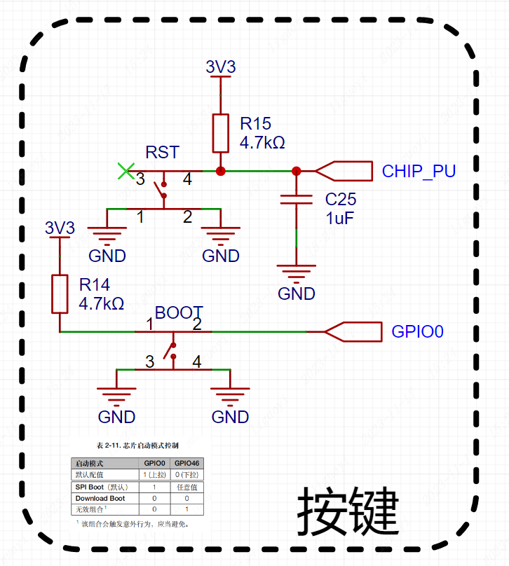
This example uses the onboard BOOT button on the development board. The BOOT button is connected to GPIO0 of the ESP32S3 chip, and the LED is connected to GPIO48. We need to configure button pin GPIO0 as an external interrupt pin and LED pin GPIO48 as output mode, then use the button to control the LED on and off.
6.6 External Interrupt Verification
#define BUTTON 0
#define LED 48

// LED state
bool led_flag = false;
// Button state. Variables shared by the interrupt callback and main program must use the volatile keyword.
volatile bool flag = false;

// Interrupt callback function
void ISR()
{
  flag = true;
}

void setup()
{
  // Set the KEY pin (0) to pull-up input mode
  pinMode(BUTTON, INPUT_PULLUP);

  // Set the LED pin (48) to output mode
  pinMode(LED, OUTPUT);

  // Configure GPIO0 as the interrupt pin. The external interrupt callback is ISR(), triggered on falling edge.
  attachInterrupt(digitalPinToInterrupt(BUTTON), ISR, FALLING);
}

void loop()
{
  // When the button is pressed, a falling edge is generated and ISR() is entered.
  // ISR() only sets flag = true.
  // Therefore, when flag == true, it means the button has been pressed.
  if ( flag == true )
  {
    // Delay for 200 ms
    delay(200);
    // Invert the LED state
    digitalWrite(LED, led_flag=!led_flag);

    // Reset the interrupt flag
    flag = false;

  }
}6.7 External Interrupt Effect
Press the button to turn the LED on, press it again to turn the LED off, and repeat.