

This article is originally from the open-source project LCSC ESP32S3 Functional Expansion Board by user [Xiaohan Electronic Studio] on the LCSC open-source platform.
With the review and consent of the original author, it was further supplemented by LCSC-Openkits(LCKFB).
Here we specifically note that the original copyright of the project source code belongs to Xiaohan Electronic Studio. We express our deep respect and gratitude to the developer Xiaohan Electronic Studio for their open-sharing spirit and contributions to the open-source community.
[Open-source license: CC BY-SA 3.0]
1. Project Background
To design a functional expansion board that allows you to learn ESP32 the same way you would learn a 51 microcontroller, it must include several essential modules of a 51 MCU development board:
The most representative feature of ESP32 — of course — is Wi-Fi and Bluetooth communication.
2. Hardware Design
The complete schematic is as follows:
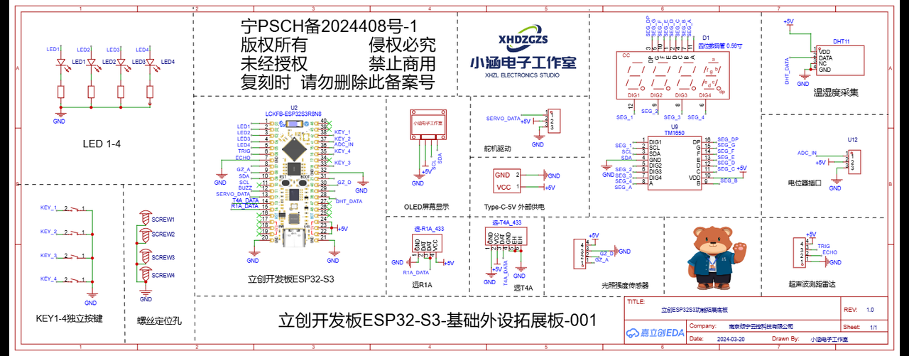
2.1 Development Board Section
2.1.1 Development Board Introduction
The LCSC ESP32S3R8N8 development board uses the ESP32-S3R8 as its main controller. The ESP32-S3 is a low-power MCU system-on-chip (SoC) released by Espressif Systems. It is dual-core and supports 2.4 GHz Wi-Fi and Bluetooth® LE (low-power Bluetooth) wireless communication. Compared with earlier ESP32 chips, the ESP32-S3 offers better speed, faster Wi-Fi, and stronger overall performance. It is also built with a more advanced process, which lowers its power consumption. Among its name, R8N8 — R8 means it has 8MB of internal PSRAM, and N8 means it has 8MB of external FLASH, achieving dual 8MB of memory.
2.1.2 Development Board Features
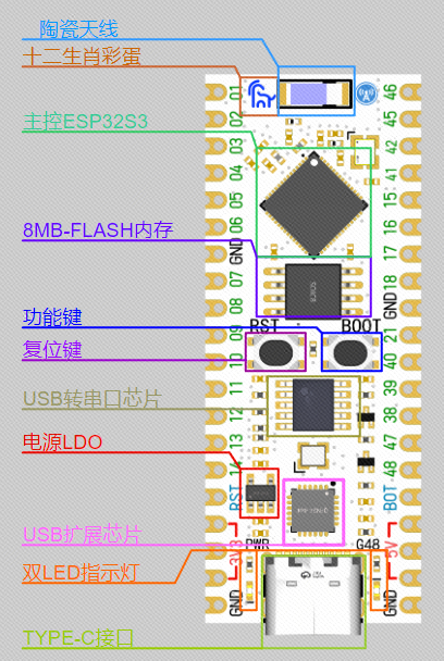
2.1.3 Development Board Source
Purchase link
Documentation download link
2.1.4 Interface Design
The development board is the main controller. As long as you power it and connect the module interfaces you want to control or read from, it is ready to go.
2.2 LED
2.2.1 Structure
An LED (light-emitting diode) is a semiconductor light source. Its main structure includes the following parts:
- Housing: usually made of plastic or glass, used to protect the internal components.
- Light-emitting material: the core part of the LED, made of special semiconductor materials, such as the common InGaN (indium gallium nitride) or AlInGaP (aluminum indium gallium phosphide).
- Chip: the LED chip used to produce light.
- Leads: metal leads that provide electrical connection.
- Solder joints: the soldered points that connect the LED chip to the leads.
- Electrodes: responsible for connecting the semiconductor material to the external circuit, usually made of metal.
- Reflective cavity: a structure used to enhance the lighting effect by reflecting the emitted light to the front.
2.2.2 Principle of Emission
The principle of LED (light-emitting diode) emission is based on semiconductor properties. In a semiconductor, there are two types of carriers: electrons (n-type semiconductor) and holes (p-type semiconductor). When n-type and p-type semiconductor materials come into contact, a junction is formed at the interface. When an appropriate voltage is applied, holes and electrons in the junction recombine and release energy. This energy is released in the form of photons, producing light.
2.2.3 Driving Principle
LED driving means providing a stable power source with appropriate current and voltage to make the LED operate and light up normally. There are two main LED driving methods: constant current and constant voltage. Constant current driving with a limited current is the most common method, because LEDs are sensitive to current — a current higher than the rated value may damage the LED. Constant current driving guarantees stable current and therefore the safety of the LED.
LED driving is relatively simple. You only need to connect the positive and negative terminals of the LED to the positive and negative terminals of the MCU. There are also two ways to connect an LED: current sinking and current sourcing.
Current sinking means the LED supply current is provided externally, and the current is sunk into our MCU. The risk is that when the external power supply changes, it may damage the MCU pin.
Current sourcing means the MCU provides voltage and current, sourcing the current to the LED. If you drive the LED directly with the MCU's GPIO, the driving capability is weak and may not provide enough current to drive the LED.
Note that different LED colors correspond to different voltages. The current must not be too large. Usually you need to connect a current-limiting resistor of about 220 ohms to 10K ohms. The larger the resistance of the current-limiting resistor, the dimmer the LED.
2.2.4 Interface Design
This expansion board uses the current-sourcing connection, with a unified current-limiting resistor of 1KΩ.
2.3 Button
2.3.1 Button Basics
2.3.2 Button Structure
The main structural components of an independent button include: the cap, the housing, the spring, the contacts, the conductive sheet, and the pins. When the button is pressed, the conductive sheet touches the contacts, forming a closed circuit.
2.3.3 Button Principle
The principle of an independent button is mainly based on the relationship between mechanical contacts and electrical contacts. When the button is not pressed, the contacts are usually separated and the circuit is open. When the user presses the button, the contacts close under the action of the spring and the conductive sheet. At this moment, the circuit is connected and the microcontroller can read the signal triggered by the button.
2.3.4 Button Driving Principle
The independent button is driven so that the microcontroller can recognize the button state, and the microcontroller happens to be able to recognize high and low levels. Therefore, most buttons are wired by connecting one terminal to a high level and the other to a GPIO, or by connecting one terminal to a low level and the other to a GPIO. By detecting whether the level on the pin connected to the button changes, the microcontroller can know whether the button is pressed.
2.3.5 Button Interface Design
In the schematic of the expansion board, the four pins of the development board are directly connected to four buttons. The detection method used is to connect one terminal of the button to a low level and the other terminal to a GPIO. When no button is pressed, it defaults to a high level through software configuration; when the button is pressed, the button pin is pulled down to a low level of 0V. This change between high and low levels allows the development board to detect the button state.
2.4 Digital Tube (Seven-Segment Display)
This development board uses a 0.56-inch common-cathode 4-digit digital tube, driven by the TM1650 (SOP-16) chip based on the I2C bus protocol.
2.4.1 Introduction to Digital Tube and Driver
Digital tubes are usually used to display numbers or certain characters, while the TM1650 is an integrated circuit (IC) used to drive digital tubes. It communicates with the main controller (such as Arduino, STM32, etc.) via the I2C protocol and can drive multi-digit digital tubes.
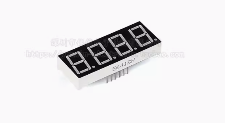
2.4.2 Component Source
 |  |
|---|---|
2.4.3 Specifications
2.4.4 Interface Design
0.56-inch 4-digit common-cathode digital tube
2.5 Potentiometer
2.5.1 Potentiometer Introduction
A potentiometer is a variable resistor with three terminals, usually used to adjust the output of voltage or current. By rotating or sliding its moving contact, the potentiometer changes its resistance value, thereby adjusting the voltage and current in electrical equipment.
2.5.2 Potentiometer Structure
A potentiometer is mainly composed of the following parts:
- Fixed resistor: the basic resistive track, usually made of carbon film, resistance wire, or conductive plastic.
- Sliding contact: also known as the "moving contact", which moves along the fixed resistive track by rotating or sliding, thereby changing the resistance value of the potentiometer.
- Housing and shaft: provide mechanical support and user interface, usually with a knob or slider for user operation.
2.5.3 Working Principle
A potentiometer changes the resistance value between two terminals by moving the sliding contact along the fixed resistive track. Specifically, a potentiometer has three terminals:
- Two external terminals: connected to both ends of the fixed resistive track.
- One middle terminal (sliding contact): connected to a movable contact that changes its position on the resistive track by rotating or sliding. As the sliding contact moves, the divided resistance value on the resistive track also changes, which in turn changes the output voltage or current.
2.5.4 Potentiometer Source
Purchase link
2.5.5 Specifications
2.5.6 Interface Design
There are three interfaces on the potentiometer module: VCC and GND are used for power supply, and OUT is the sliding-value output port of the potentiometer. Based on this principle, the expansion board is designed as follows:
2.6 Servo Driver
2.6.1 Servo Introduction
This expansion board uses the SG90 servo module. The SG90 servo is a common small servo motor, widely used in model airplanes, robots, robotic arms, and other projects. It consists of high-precision servo control electronics and a motor. It can rotate within a certain range and hold its position, and is usually used in places where precise angle control is required.
2.6.2 Servo Features
- Compact and lightweight: The SG90 servo has a compact design and weighs only about 9 grams, making it ideal for small electronic projects and models.
- Easy to control: The servo's rotation angle is controlled via a standard PWM (Pulse Width Modulation) signal, compatible with most microcontrollers and development boards.
- High precision and fast response: It uses an internal feedback system to control position, featuring high precision and fast response.
2.6.3 Module Source
Purchase link:
Left column content SG90MG90s 9g servo MG995/996R helicopter fixed-wing RC airplane motor model robot
Documentation download:
https://pan.baidu.com/s/1QsTIKnoQsOTCkeYLLTTjTA?pwd=8889
Extraction code: 8889
When purchasing, you need to determine whether your servo can rotate 180 degrees or 360 degrees. A 360-degree servo cannot control the angle, it can only control the rotation speed.
The rotation speed of the SG90 servo is not very fast, generally 0.22/60 degrees or 0.18/60 degrees. So if you change the width of the angle-control pulse too quickly, the servo may not be able to respond in time. If you need a faster response, a higher rotation speed is required.
2.6.4 Specifications
Specifications
Drive voltage: 3V~7.2V
Operating torque: 1.6KG/CM
Control method: PWM
Rotation angle: 180 degrees
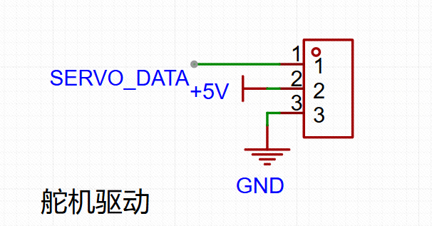
2.6.5 Interface Design
Servo interface: usually comes with three wires (brown, red, and orange)
- Brown: Ground (GND)
- Red: Power (VCC)
- Orange: PWM control signal
2.7 Temperature and Humidity Acquisition
2.7.1 Sensor Introduction
Thanks to the rapid development of integrated circuit technology in the world, the industry now has mature modular solutions for temperature and humidity acquisition. The temperature and humidity module used on the expansion board is the DHT11 temperature and humidity sensor. The DHT11 is a commonly used temperature and humidity sensor that can simultaneously measure ambient temperature and humidity. It is widely used in various projects that require environmental monitoring, such as home automation, weather stations, and automatic control systems. The DHT11 is a low-cost, easy-to-use sensor with calibrated digital signal output, and it can acquire temperature and humidity using only a single data wire, making it very suitable for beginners.
2.7.2 Basic Features
- Temperature and humidity measurement: can simultaneously measure ambient temperature and humidity.
- Digital signal output: uses a single data wire to transmit measurement results, making it easy to connect with microcontrollers.
- Low cost: suitable for low-budget projects.
- Easy to use: simple to program and connect, suitable for beginners and educational use.
2.7.3 Module Source
Purchase link:
DHT11 temperature module, humidity module, temperature and humidity module, DHT11 sensor
You can also purchase directly from LCSC, part number: C117051
Documentation download link: https://pan.baidu.com/s/1HQEL699-Yl5Jh3Hp87_FlQ
Documentation extraction code: 2sgq
2.7.4 Specifications
Specifications
Operating voltage: 3-5.5V
Operating current: 1mA
Measurement resolution: 8 bit
Humidity range: 20 - 90 %RH
Humidity accuracy: ±5 %RH
Temperature range: 0 - 50 ℃
Temperature accuracy: ±2 ℃
Communication protocol: single-wire bus
Number of pins: 3 Pin (2.54mm pitch header)
2.7.5 Interface Design
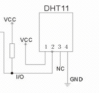
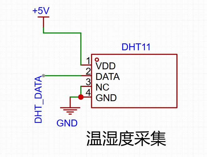
According to the typical application circuit in its datasheet, the hardware interface of the module can be designed directly.
2.8 OLED Screen Display
2.8.1 Screen Introduction
This expansion board uses a 0.96-inch OLED screen with an I2C interface. The 0.96-inch OLED screen (typically 128x64 resolution) with an I2C interface is a display module widely used in various electronic projects in recent years. It combines the advantages of high brightness, high contrast, and low power consumption, and is commonly used in microcontroller projects, embedded systems, and DIY electronics.
2.8.2 Basic Parameters and Features
- Size: 0.96 inch
- Resolution: 128x64 pixels
- Interface type: I2C interface (some models also support SPI interface)
- Driver chip: SSD1306
- Display color: monochrome (usually white, blue, or yellow)
- Viewing angle: nearly 180 degrees
- Power consumption: usually low, suitable for battery-powered portable devices
- Operating voltage: usually 3.3V or 5V (some models are compatible with both voltages)
2.8.3 Module Source
Purchase link:
0.96-inch OLED display 12864 LCD module I2C display SSD1306 12864 OLED
Documentation download link:
https://pan.baidu.com/s/1xy2zH8-hs-S8-_AcVtBP_g
Documentation extraction code: 0jhj
2.8.4 Interface Design
This screen requires 4 interfaces. For specific interface descriptions, see the pin descriptions in Table 1.
Therefore, in the design of the expansion board, the connections are as follows: (SCL and SDA are connected to development board pins SCL=10, SDA=9)
2.9 Light Intensity Acquisition
2.9.1 Light Acquisition Introduction
For the light acquisition function, the expansion board mainly uses a photoresistor. It is a special resistor made of semiconductor materials such as cadmium sulfide or cadmium selenide, and its working principle is based on the internal photoelectric effect. As the light intensity increases, the resistance value drops rapidly, because the carriers generated by light all participate in conduction and drift under the applied electric field — electrons run toward the positive pole of the power supply, and holes run toward the negative pole of the power supply, causing the resistance of the photoresistor to drop rapidly. When there is no light, it is almost in a high-resistance state, with a very large dark resistance. Photoresistor modules are generally used to detect the brightness of ambient light, triggering an MCU or relay module, etc.
In short, a photoresistor is a special resistor whose resistance value drops rapidly as the light intensity increases. When there is no light, it is almost in a high-resistance state, so the dark resistance is very large.
The most common module on the market for detecting light uses a photoresistor as the main sensing component. Its schematic is shown on the right. U2.1 in the schematic is a voltage comparator. When the voltage at pin 2 of the comparator is greater than the voltage at pin 3, pin 1 outputs a low level; when the voltage at pin 2 is less than the voltage at pin 3, pin 1 outputs a high level. R3 is the photoresistor. When the ambient environment around the photoresistor is very bright, its resistance becomes smaller, and the AO voltage also becomes smaller; when the ambient environment around the photoresistor is very dark, its resistance becomes larger, and the AO voltage also becomes larger. Therefore, by adjusting the resistance of the R4 sliding resistor, the sensitivity of the DO output can be adjusted.
2.9.2 Module Source
Photoresistor sensor module, light sensing, smart car accessories
Documentation download link: https://pan.baidu.com/s/1VMFN1fVo5jxB80IYTsY67A
Documentation extraction code: y8jw
2.9.3 Specifications
Operating voltage: 3.3-5V
Operating current: 1mA
Module size: 31.1475 x 14.097mm
Output mode: DO interface for digital output, AO interface for analog output
Read method: ADC
Number of pins: 4 Pin (2.54mm pitch header)
2.9.4 Interface Design
Here, to save cost, we recommend directly using modules available on the market.
2.10 Ultrasonic Radar Ranging
2.10.1 Ultrasonic Introduction
To save cost, the expansion board also adopts a modular design. It uses the commonly available ultrasonic module on the market: the SR04 ultrasonic ranging sensor. The SR04 ultrasonic ranging module (HC-SR04) is a commonly used distance measurement sensor, widely used in robot navigation, obstacle detection, automatic control, and other fields. This module uses the ultrasonic reflection principle to measure the distance between an object and the sensor by sending and receiving ultrasonic signals.
Purchase link: HC-SR04 Ultrasonic ranging module, wide voltage 3-5.5V, industrial grade, sensor
Documentation download link: https://pan.baidu.com/s/1sSah9PvLBrmbA7So-6YcSw
Documentation extraction code: qq35
2.10.3 Basic Principle
The HC-SR04 is mainly composed of an ultrasonic transmitter, an ultrasonic receiver, and a control circuit. Its working process is as follows:
- Transmitting ultrasonic waves: The module emits a 40kHz ultrasonic pulse through the transmitter.
- Ultrasonic propagation: The ultrasonic wave propagates through the air and reflects back when it hits an obstacle.
- Receiving ultrasonic waves: The module receives the reflected ultrasonic wave through the receiver.
- Calculating distance: The distance is calculated based on the time it takes for the ultrasonic wave to travel from emission to reception and the speed of sound in air (approximately 343 meters/second).
2.10.4 Specifications
Operating voltage: 5-5.5V
Operating current: 5.3mA
Sensing angle: less than 15 degrees
Detection distance: 2CM-600CM
Detection precision: 0.1CM+1%
Output mode: GPIO
Number of pins: 4 Pin
2.10.5 Interface Design
Module pin description:
- VCC: Power positive (5V)
- Trig: Trigger pin (connected to the microcontroller's output pin, sends the trigger signal)
- Echo: Echo pin (connected to the microcontroller's input pin, receives the echo signal)
- GND: Ground (power negative)
2.11 433.92MHz RF Communication
2.11.1 YuanR1-A (RF Receiver)
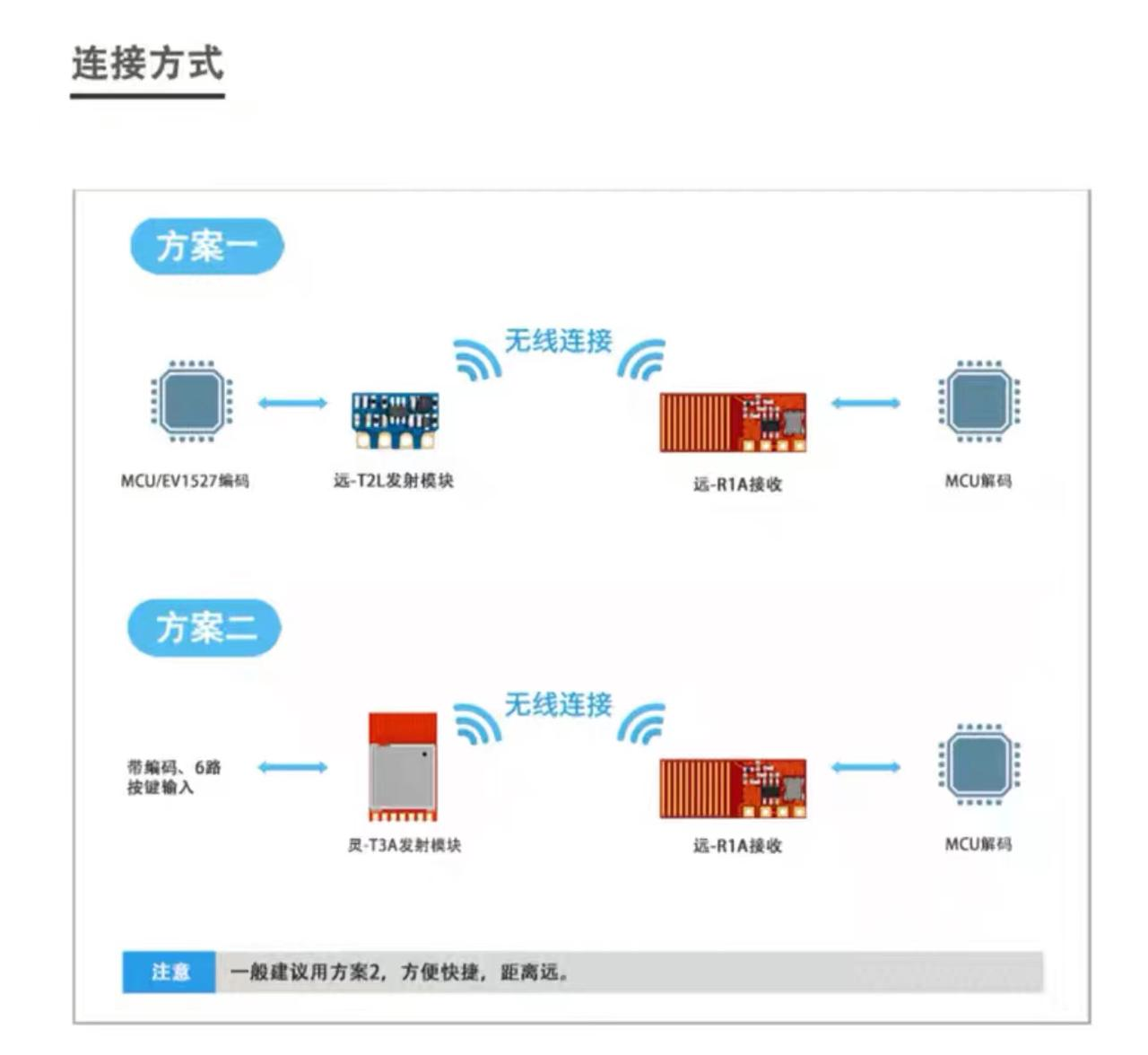
The Hummingbird Wireless YuanR1-A is a high-performance wireless receiver module. It features high sensitivity and long-distance reception capability, suitable for various wireless remote control applications. The module adopts a high-performance RF integrated chip, internally integrating an RF amplifier, mixer, IF amplifier, frequency synthesizer, automatic gain control, filter, demodulator, and other functions. The YuanR1-A comes with a high-gain antenna, supports long-distance remote control, and its pins are compatible with "Yuan-R1" and "Yuan-R1L". This module is widely used in home appliance remote control, remote control switch sockets, electric curtains, security alarms, wireless light control, pagers, and other fields. The operating frequency is 315/433.92MHz (default), the operating voltage range is 2.0-5.5V, and it has a low-power design with an operating current of only 2.95mA.
2.11.2 Module Source
Purchase link: Hummingbird wireless module Yuan-R1A, 433M smart home remote control dedicated
For documentation, please refer to the Taobao product page or contact Taobao customer service.
2.11.3 Specifications
Voltage: 2.0V-5.5V
Current: 2.95mA
Frequency: 433.92MHz
2.11.4 Interface Design
2.11.5 YuanT4-A (RF Transmitter)
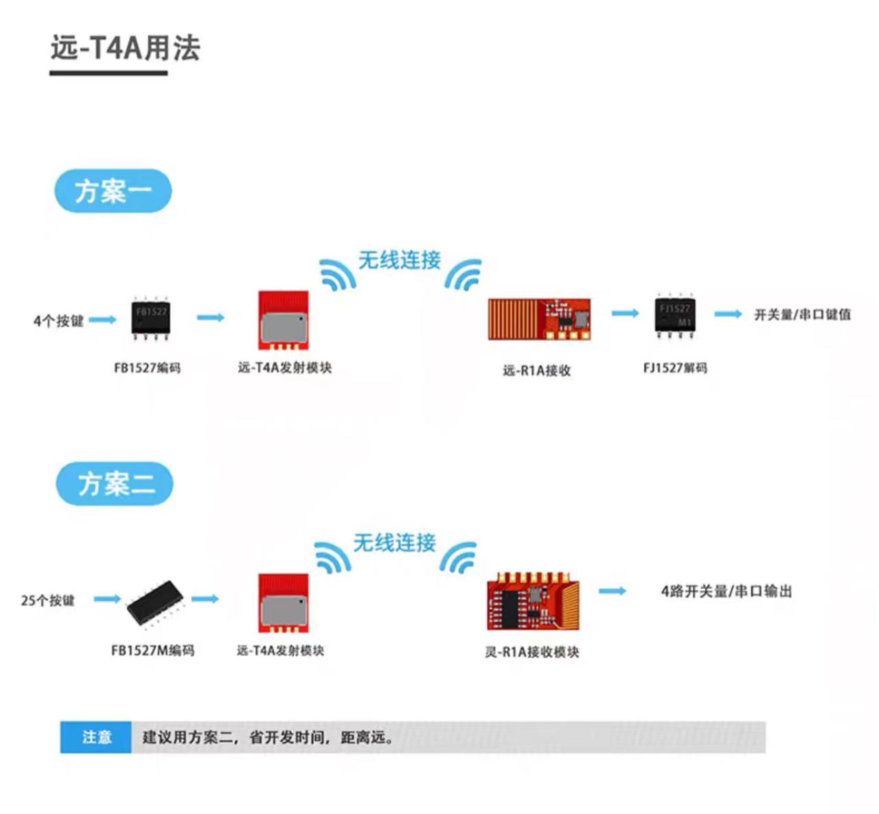
The Hummingbird Wireless YuanT4-A delivers outstanding performance in many fields such as wireless doorbells, car remote controls, remote control toys, wireless light control, smart home, and smart appliances. It supports ASK modulation, 315/433MHz carrier, 1kbps modulation square wave, and 1527 decoding.
2.11.6 Module Source
Purchase link: Hummingbird wireless module Yuan-T4A, smart home remote control 433M, FCC certified
For documentation, please refer to the Taobao product page or contact Taobao customer service.
2.11.7 Specifications
Voltage: 2.0V-5.5V
Current: 10mA
Frequency: 433.92MHz
2.11.8 Interface Design
3. Software Design
3.1 Development Board
3.1.1 Development Environment Introduction
The overall project is written using the Arduino IDE. The Arduino IDE (Integrated Development Environment) is an open-source software mainly used for writing, compiling, and uploading code to Arduino-compatible microcontroller boards. It provides a simple and easy-to-use interface and supports multiple programming languages, especially C and C++. The Arduino IDE also comes with a large number of examples and libraries, making hardware programming easier, even for beginners.
3.1.2 Main Features of Arduino IDE
- User-friendly interface: easy to navigate and use, suitable for beginners.
- Cross-platform support: runs on Windows, macOS, and Linux operating systems.
- Rich libraries and examples: built-in libraries and example code to help quickly develop projects.
- Board Manager: allows easy installation and management of support packages for different Arduino-compatible boards.
- Serial Monitor: a built-in serial monitor for debugging, viewing microcontroller output through the serial port.
- Extension support: functionality can be extended through plugins and additional libraries.
3.1.3 Arduino IDE and ESP32S3 Support
The ESP32S3 is a low-power Wi-Fi and Bluetooth dual-module microcontroller developed by Espressif Systems. Although the Arduino IDE was originally developed for the Arduino series hardware, to date the Arduino IDE has been extended to support other microcontrollers, including the ESP32.
3.1.4 Environment Setup
For the Arduino IDE environment setup for the ESP32S3 development board, please refer to the development board's official Arduino beginner manual!
To verify whether the setup is successful, please follow the LED lighting chapter in the beginner manual for verification.
3.2 LED
This chapter uses driving LEDs LED1-LED4 on the expansion board to blink simultaneously as an experiment. For a detailed description of the code, refer to the LED Driver Flow chapter of the ESP32S3R8N8 development board Arduino beginner manual.
int led1 = 1; // LED1-4 pins
int led2 = 2;
int led3 = 3;
int led4 = 4;
void setup() {
  pinMode(led1, OUTPUT); // Configure all LED1-4 pins as output mode
  pinMode(led2, OUTPUT);
  pinMode(led3, OUTPUT);
  pinMode(led4, OUTPUT);
}

void loop() {
  digitalWrite(led1, HIGH); // Since the schematic uses common-cathode LEDs, the LEDs light up at high level
  digitalWrite(led2, HIGH);
  digitalWrite(led3, HIGH);
  digitalWrite(led4, HIGH);
  delay(1000); // Keep lit for one second
  digitalWrite(led1, LOW); // Turn off
  digitalWrite(led2, LOW);
  digitalWrite(led3, LOW);
  digitalWrite(led4, LOW);
  delay(1000); // Keep off for one second
}Because GPIO1~GPIO4 on the development board are connected to the 4 LEDs on the expansion board, GPIO1 to GPIO4 on the development board are respectively set as output pins. The LED blinking is achieved through the delay function.
3.3 Button-Controlled LED
Press the button to light up the LED, release to turn off the LED.
int led1 = 1; // LED1-4 pins
int led2 = 2;
int led3 = 3;
int led4 = 4;

int key1 = 41; // Pins for buttons 1-4, PCB has an error, follow the code
int key2 = 18;
int key3 = 42;
int key4 = 16;
void setup() {
  pinMode(led1, OUTPUT); // Configure all LED1-4 pins as output mode
  pinMode(led2, OUTPUT);
  pinMode(led3, OUTPUT);
  pinMode(led4, OUTPUT);

  pinMode(key1, INPUT_PULLUP); // Configure buttons 1-4 as input mode with internal pull-up
  pinMode(key2, INPUT_PULLUP);
  pinMode(key3, INPUT_PULLUP);
  pinMode(key4, INPUT_PULLUP);
}

void loop() {
  if (!digitalRead(key1)) { // Light up all LEDs depending on which button is pressed
    digitalWrite(led1, HIGH);
  }
  else if (!digitalRead(key2)) {
    digitalWrite(led2, HIGH);
  }
  else if (!digitalRead(key3)) {
    digitalWrite(led3, HIGH);
  }
  else if (!digitalRead(key4)) {
    digitalWrite(led4, HIGH);
  }
  else {
    digitalWrite(led1, LOW); // If none is pressed, turn off all LEDs
    digitalWrite(led2, LOW);
    digitalWrite(led3, LOW);
    digitalWrite(led4, LOW);
  }
}3.4 Digital Tube Display
Scroll display of the characters "ESP32-S3-JLC".
The code uses two libraries: wire.h and TM1650.h. wire.h is a built-in file in the Arduino IDE and can be used directly. TM1650.h needs to be downloaded from the Arduino IDE Library Manager.
Install the library file (if already installed, ignore this)
- Open Arduino IDE.
- Select "Tools" > "Manage Libraries…".
- Search for "TM1650", then install this library.
Actual code:
#include <Wire.h>
#include <TM1650.h>

TM1650 SEG;

void setup() {
  Wire.begin();
  SEG.init();
}

void  loop(){
  if (SEG.displayRunning("    ESP-32-S3-JLC   ")) {
    while (SEG.displayRunningShift()) delay(555);
  }
}3.5 Potentiometer
Output the raw data of the potentiometer (0-4095) on the serial port.
int adc_pin = 15;
void setup(){
  Serial.begin(115200);
  pinMode(15,INPUT);
}

void loop(){
  Serial.printf("Potentiometer raw data: %d\r\n",analogRead(15));
  delay(600);
}3.6 Servo Driver
For this function, you must connect the Type-C power supply of the expansion board, otherwise the computer may show a blue screen.
Drive the servo to rotate cyclically from 0 degrees -> 90 degrees -> 180 degrees.
The code uses a library: ESP32Servo.h. It needs to be downloaded from the Arduino IDE Library Manager.
Install the library file (if already installed, ignore this)
- Open Arduino IDE.
- Select "Tools" > "Manage Libraries…".
- Search for "ESP32Servo", then install this library.
Actual code:
#include<ESP32Servo.h>
Servo TEST_SERVO;

void setup() {
  TEST_SERVO.attach(12); // Define the GPIO of the servo
}

void loop() {
  TEST_SERVO.write(0);   // 0 degrees
  delay(555);
  TEST_SERVO.write(90);  // 90 degrees
  delay(555);
  TEST_SERVO.write(180); // 180 degrees
  delay(555);
}3.8 OLED Screen Display
Display text on the OLED screen.
Install the library file (if already installed, ignore this)
- Open Arduino IDE.
- Select "Tools" > "Manage Libraries…".
- Search for "Adafruit SSD1306" and "Adafruit GFX", then install these two libraries respectively.
#include <Adafruit_GFX.h>
#include <Adafruit_SSD1306.h>

Adafruit_SSD1306 display(128, 64, &Wire, -1);

void setup() {
  display.begin(SSD1306_SWITCHCAPVCC, 0x3C);
  display.clearDisplay();
  display.setTextSize(1);
  display.setTextColor(WHITE); // No need to change, default is fine
  display.setCursor(0, 10);
  display.println("Hello JLC");
  display.setCursor(0, 30);
  display.println("Hello LCKFB ESP32 S3");
  display.setCursor(0, 50);
  display.println("Hello XIAOHAN");
  display.display();
}

void loop() {
  delay(1000);
}The code for displaying a smooth animation on the OLED screen is included in the source file at the bottom of this document. The content is too large to be placed in the document.
3.9 Ultrasonic Radar Ranging
#define PIN_TRIG 5
#define PIN_ECHO 6

void setup() {
  Serial.begin(115200);
  pinMode(PIN_TRIG, OUTPUT);
  pinMode(PIN_ECHO, INPUT);
}

void loop() {
  digitalWrite(PIN_TRIG, HIGH);
  delayMicroseconds(10);
  digitalWrite(PIN_TRIG, LOW);

  int duration = pulseIn(PIN_ECHO, HIGH);
  Serial.print("cm: ");
  Serial.println(duration / 58);
  Serial.print("inch: ");
  Serial.println(duration / 148);

  delay(1000);
}3.10 Light Intensity Acquisition
int adc_pin = 7;
void setup(){
  Serial.begin(115200);
  pinMode(15,INPUT);
}

void loop(){
  Serial.printf("Light raw data: %d\r\n",analogRead(7));
  delay(600);
}3.11 433.92MHz RF Communication
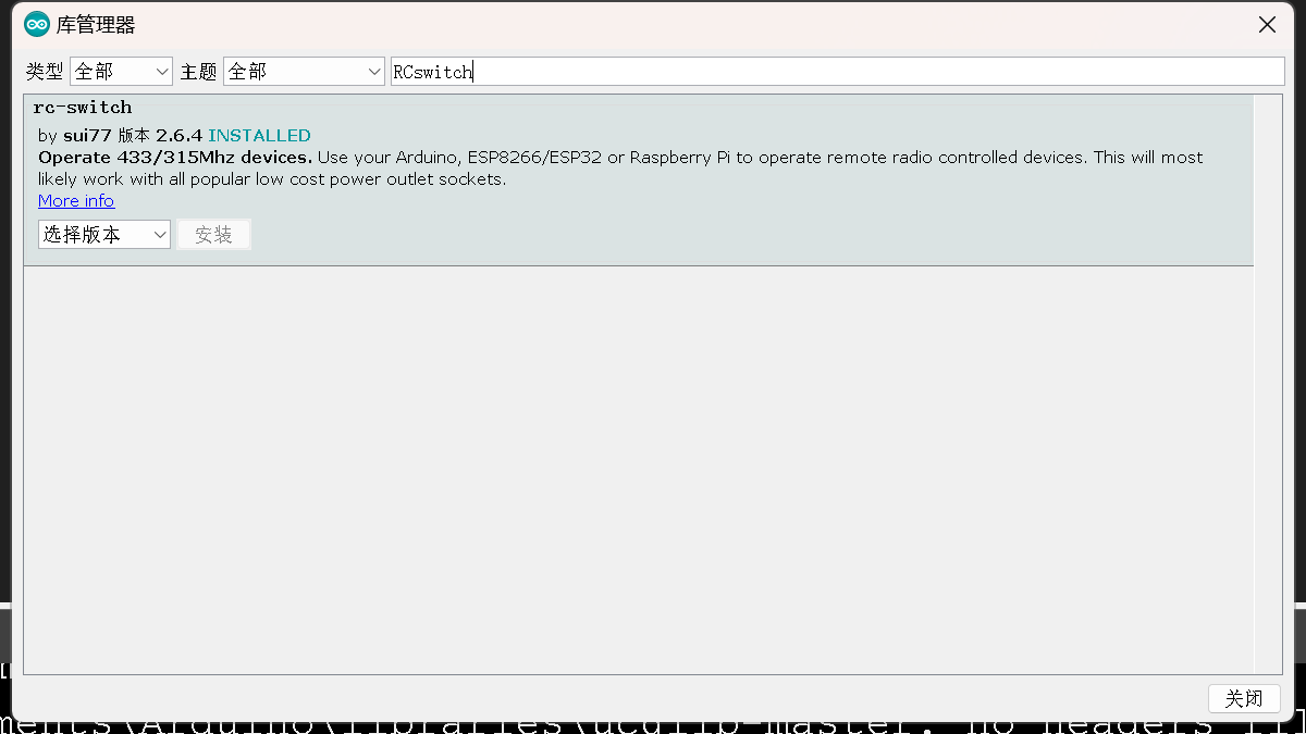
To use this function, you need to install a library: RCSwitch.h.
RF remote control receiver
#include <RCSwitch.h>

RCSwitch mySwitch = RCSwitch();

void setup() {
  Serial.begin(115200);
  mySwitch.enableReceive(14);
}

void loop() {
  if (mySwitch.available()) {
    Serial.print("Received ");
    Serial.print( mySwitch.getReceivedValue() );
    Serial.print(" / ");
    Serial.print( mySwitch.getReceivedBitlength() );
    Serial.print("bit ");
    Serial.print("Protocol: ");
    Serial.println( mySwitch.getReceivedProtocol() );
    mySwitch.resetAvailable();
  }
  delay(666);
}RF remote control transmitter
#include <RCSwitch.h>

RCSwitch mySwitch = RCSwitch();

void setup() {
  mySwitch.enableTransmit(13); // Initialize YuanT4-A
}

void loop() {
  mySwitch.send(1234, 24); // Send RF code 1234 once per second
  delay(1000);
}Summary
Download the source code of all examples.
File download
Download from the Download Center Baidu Netdisk link -> Project Cases -> LCSC ESP32S3 Functional Expansion Board!!
Download the directly compiled comprehensive test firmware.
File download
Download from the Download Center Baidu Netdisk link -> Project Cases -> LCSC ESP32S3 Functional Expansion Board!!
Firmware download tool
File download
Download from the Download Center Baidu Netdisk link -> Project Cases -> LCSC ESP32S3 Functional Expansion Board!!
Onboard CH340 driver
File download
Download from the Download Center Baidu Netdisk link -> Project Cases -> LCSC ESP32S3 Functional Expansion Board!!
Acknowledgements to Strategic Partners Nanjing Qingning Yuncontrol Technology Co., Ltd.
Thanks to JLCEDA Pro for providing PCB design support.
Thanks to Lingchengxin Electronics (Hummingbird Wireless) for providing RF module consumables support.
Thanks to Diandeng Technology (Chengdu) Co., Ltd. for providing mobile APP usage support.
Thank you all for reading this far! If you like this project, get started and have fun with JLC's free prototyping service! I'm Xiaohan. Welcome to join the following study and exchange group! See you in the next project!
Group number: 873075959
For reprinting, please contact the author for permission. Permission will generally be granted without excessive requirements. After reprinting, please indicate the source and attach the project link: https://oshwhub.com/xiaohanxdzdy/li-chuang-development-board-esp32s3-r8n8-function-expansion-backplane