10. I2C
10.1 What is I2C
The IIC (Inter-Integrated Circuit) protocol, also known as the I2C bus, is a serial communication protocol typically used to connect low-speed peripherals. It was developed by Philips (now NXP Semiconductors) in the early 1980s and has now become a standard. The IIC bus requires only two data lines: the Serial Data Line (SDA) and the Serial Clock Line (SCL), which makes it a very simple interface. It is suitable for chip-based communication, such as connecting sensors, memory, or digital signal processors.
In the IIC protocol, there is one master device and multiple slave devices on the bus. The master device controls the communication process on the bus, responsible for initiating, controlling, and stopping communication. The slave devices need to wait for requests from the master device to receive or send data. Data exchange between the master device and slave devices uses a frame format, where each frame usually contains address, data, and control information. The master device selects the device to communicate with based on the slave device's address, and the slave device performs corresponding operations based on the control information. The IIC protocol can support multiple slave devices connected to the same master device, providing greater flexibility for system design. 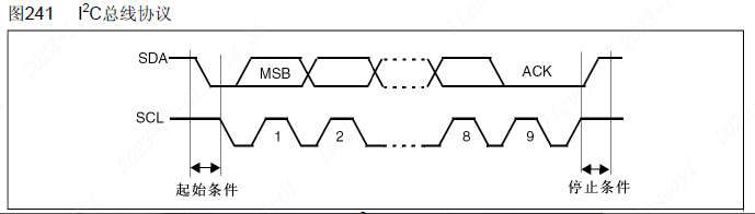
10.2 Hardware Implementation of I2C
The I2C bus typically uses two voltage levels: high level (VH) and low level (VL). The high level is 2.5V to 5.5V, and the low level is 0V to 0.3V; these voltage level ranges are determined according to the I2C specification.
The I2C bus has different transmission rates available, including standard mode (100 kbps), fast mode (400 kbps), and high-speed mode. The choice of transmission rate depends on the application requirements and the device's support capabilities.
To avoid signal conflicts, the microprocessor (MCU) must only drive SDA and SCL low, that is, open-drain output. Setting it to open-drain mode is mainly to protect devices and prevent interference.
- Prevent interference: Multiple devices share the same data line (SDA) and the same clock line (SCL). If push-pull output mode is used, the outputs of multiple devices will overlap on the data line, causing signal interference, and in severe cases, damaging devices or causing communication errors. With open-drain output mode, the outputs of each device only have the part that pulls the data line low, and will not interfere with each other, thereby improving the reliability and anti-interference ability of the bus.
- Prevent short circuits: In open-drain output mode, since the device's output only has the part that pulls the data line low, even if two or more devices output at the same time, no short circuit will occur. If push-pull output mode is used, when two or more devices output at the same time, a short circuit may form. For example, when the master device outputs a high level and the slave device outputs a low level.
Because it is set to open-drain mode, an external pull-up resistor (e.g., 10k) needs to be connected to pull the signal up to high level. Therefore, the SDA (data line) and SCL (clock line) in the I2C bus are usually connected to pull-up resistors to ensure the stability of the logic high level. The resistance value of the pull-up resistor is usually between 2.2kΩ and 10kΩ, depending on the capacitive load of the bus and the communication distance.
The maximum cable length and transmission capacity of the I2C bus are limited. In standard mode, the maximum cable length is about 1 meter, while in fast mode, the maximum cable length is about 0.3 meters. In addition, the bus capacitance on the cable also affects the transmission rate. 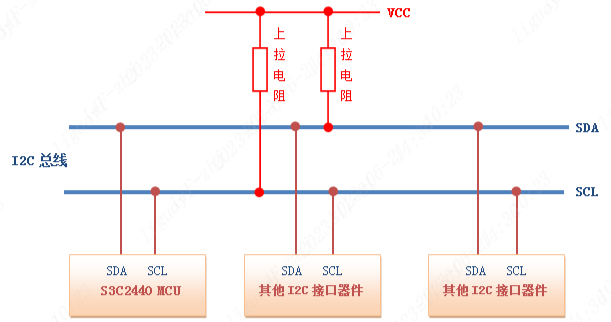
10.3 I2C Data Transmission
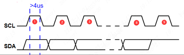
The I2C protocol uses a bus arbitration mechanism for data transmission. It has only two communication lines, so its data transmission is based on the clock signal. The clock is generated by the master device and controls the data transmission rate. Data is sent and received by the master device, but the exchange is achieved through the acknowledgement of the slave device.
The following are several important timing sequences of the IIC bus:
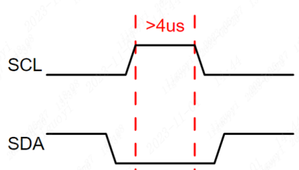
Start signal: When SCL is high, the SDA level transitions from high to low, indicating the start of a communication.
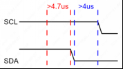
void IIC_Start(void)
{
    SDA_OUT(); // Set SDA to output mode
    SDA(1);
    SCL(1);
    delay_us(5);
    SDA(0);
    delay_us(5);
    SCL(0);
    delay_us(5);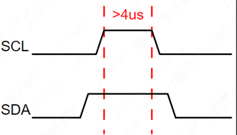
}Stop signal: When SCL is high, the SDA level transitions from low to high, indicating the end of this communication. After sending the stop signal, the master device cannot send any more data to the slave device unless it sends another start signal.
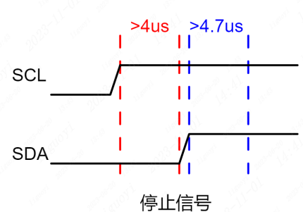
void IIC_Stop(void)
{
    SDA_OUT();
    SCL(0);
    SDA(0);

    SCL(1);
    delay_us(5);
    SDA(1);
    delay_us(5);
}
// Send one byte
void IIC_Send_Byte(unsigned char dat)
{
    int i = 0;
    SDA_OUT();
    SCL(0);
    for( i = 0; i < 8; i++ )
    {
        SDA( (dat & 0x80) >> 7 );
        delay_us(1);
        SCL(1);
        delay_us(5);
        SCL(0);
        delay_us(5);
        dat<<=1;
    }
}// Receive one byte
unsigned char IIC_Read_Byte(void)
{
unsigned char i,receive=0;
SDA_IN(); // Set SDA to input
for(i=0;i<8;i++ )
{
SCL(0);
delay_us(5);
SCL(1);
delay_us(5);
receive<<=1;
if( SDA_GET() == 1 )
{
receive |= 1;
}
}
SCL(0);
return receive;
}
 void IIC_Send_Ack(void)
{
SDA_OUT();
SCL(0);
SDA(1);
SDA(0);
SCL(1);
delay_us(5);
SCL(0);
SDA(1);
}void IIC_Send_Nack(void)
{
SDA_OUT();
SCL(0);
SDA(0);
SDA(1);
SCL(1);
delay_us(5);
SCL(0);
SDA(0);
}In the IIC bus, the clock line is controlled by the master device. Each data bit is updated on the clock edge, and the maximum transmission rate depends on the slowest device on the bus. Generally speaking, the communication rate of the IIC bus is relatively slow, usually in the range of several hundred kbps. If a higher transmission rate is required, other communication protocols such as SPI or CAN can be used.
10.4 I2C Communication Flow
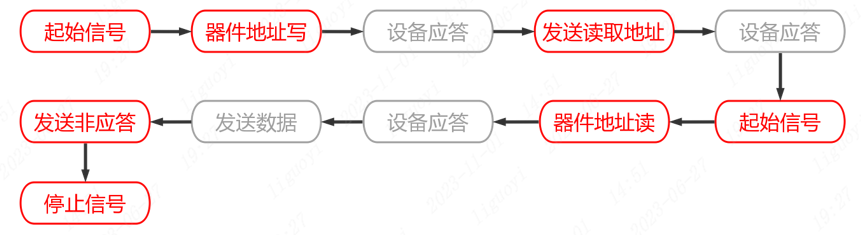
The I2C communication flow proceeds as follows:
- The master sends a start signal to the bus.
- The master sends the address of the device to communicate with and the read/write bit (R/W) onto the bus.
- The device sends an acknowledge signal after receiving the address. After the master receives the acknowledge signal, it sends data or continues sending the address.
- The device sends an acknowledge signal after receiving the data. After the master receives the acknowledge signal, it can continue sending data or stop the communication.
- The master sends a stop signal to the bus.

10.5 Basic I2C Parameters
Speed: The I2C bus has two transmission modes: standard mode (100 kbit/s) and fast mode (400 kbit/s), as well as faster extended mode and high-speed mode.
Device address: Each device has a unique 7-bit or 10-bit address. You can select who to communicate with through the address.
Bus state: The I2C bus has five states: idle state, start signal, stop signal, acknowledge signal, and data transmission.
Data format: The I2C bus has two data formats: standard format and fast format. The standard format is an 8-bit data byte plus 1 ack/nack bit. The fast format allows two bytes to be transmitted at the same time.
Since the SCL and SDA lines are bidirectional, they may also experience level errors due to external reasons (such as capacitance in the circuit, etc.), resulting in communication errors. Therefore, in the IIC bus, pull-up resistors are usually used to ensure that the signal lines are at a high level in the idle state.
10.6 Software I2C and Hardware I2C
The I2C protocol can be implemented through software or hardware. The difference between the two lies in the implementation method and the required hardware resources. 10.6.1 Software I2C Software I2C refers to implementing the I2C communication protocol by writing code in a program. It uses general-purpose input/output (GPIO) pins to simulate the I2C data line (SDA) and clock line (SCL), and transmits data and generates timing signals by controlling the pin levels through software. Compared with hardware I2C, the advantage of software I2C is that it does not require specific hardware support and can be implemented on any microcontroller that supports GPIO functions. It uses the microcontroller's general-purpose IO pins to implement the I2C communication protocol.
The implementation of software I2C simulates the master and slave devices of I2C through programming. By reading and writing the status of GPIO pins bit by bit and performing corresponding operations according to the timing requirements of the I2C protocol, data transmission and communication are achieved. Software I2C is highly flexible and can be customized and extended according to application requirements. It can handle multiple slave devices and supports multi-master environments. Therefore, software I2C is widely used in resource-constrained MCU systems, especially in applications that need to communicate with multiple external devices.
Although the performance of software I2C is relatively lower than that of hardware I2C, in scenarios with low-speed communication and simple communication requirements, software I2C is an economical and practical solution.
10.6.2 Hardware I2C
Hardware I2C refers to handling the I2C communication protocol through a dedicated hardware module. Most modern microcontrollers and some external devices have integrated hardware I2C modules. These hardware modules are responsible for handling the details of I2C communication, including generating correct timing signals, automatically handling signal conflicts, data transmission, and error detection. You can directly use hardware pins for connection without writing timing code.
Using hardware I2C is usually relatively simple. Developers do not need to write complex code to handle the details of the communication protocol. The hardware module can directly connect to external devices and transmit data and clock through dedicated pins, thereby achieving efficient and reliable communication.
When choosing between software I2C and hardware I2C, you need to consider the application requirements and hardware resources. Software I2C is suitable for resource-constrained systems and can be implemented on any microcontroller that supports GPIO, but its performance is relatively lower. Hardware I2C usually has better performance but requires hardware support and may occupy certain specific pin resources.
10.6.3 I2C Pros and Cons
10.6.3.1 Advantages
Bidirectional transmission: The I2C bus supports bidirectional transmission. Data can be transmitted between the master device and slave device simultaneously through the SDA line, saving bus resources.
System integration: The I2C bus can be quickly integrated into chips, reducing the logic complexity of system implementation and improving design efficiency.
Multi-device sharing: The I2C bus can achieve communication between multiple devices and the master controller through address transmission, allowing multiple devices to share the bus and interact directly.
High reliability: The I2C bus uses logical levels instead of electrical signals to represent data transmission, providing higher transmission reliability.
10.6.3.2 Disadvantages
Limited bandwidth: The transmission speed of the I2C bus is limited to 400 kbps. Compared with the SPI bus and CAN bus, the bandwidth is relatively low.
Strict timing requirements: The I2C bus must strictly follow the timing requirements when transmitting data, especially during high-speed transmission. The timing is susceptible to interference, causing communication failures.
Limited maximum cable length: Although the I2C bus can extend the bus length through repeaters, due to issues such as signal line interference, signal attenuation, and timing requirements, the maximum cable length is generally limited to 1~2 meters.
In summary, the I2C bus has advantages such as bidirectional transmission, system integration, and multi-device sharing, but it also has disadvantages such as relatively low transmission speed, strict timing requirements, and limited maximum cable length.
10.7 Introduction to ESP32S3 I2C
The ESP32S3 has two hardware I2C controllers (also called ports) responsible for handling communication on two I2C buses. Each I2C controller can operate as a master or a slave. The ESP32's I2C interface can be configured as master mode or slave mode, and the devices on the I2C bus can be controlled through a simple API.
10.8 I2C Usage Process
The process of using the ESP32-S3's software I2C (Serial Peripheral Interface) function in MicroPython is as follows:
- Import the relevant modules and libraries:c
import machine
2. Initialize the software I2C object:
```c
i2c = machine.SoftI2C(scl=machine.Pin(scl_pin_number), sda=machine.Pin(sda_pin_number))Where scl_pin_number and sda_pin_number are the pin numbers of the SCL (clock line) and SDA (data line) connected to the ESP32-S3.
classmachine.SoftI2C(scl, sda, *, freq=400000, timeout=255)Construct a new software I2C object. The parameters are:
- scl should be a pin object specifying the pin used for SCL.
- sda should be a pin object specifying the pin used for SDA.
- freq should be an integer used to set the maximum frequency of SCL.
- timeout is the maximum time (in microseconds) to wait for clock stretching (SCL being held low by another device on the bus) before an OSError(ETIMEDOUT) exception is raised.
- Set the I2C clock speed (optional step):
i2c.init(scl_speed=100000)Use the init() method to set the I2C clock speed. The default clock speed is 400KHz, and you can set an appropriate speed according to your needs. 4. Send I2C commands (read and write):
i2c.writeto(device_address, data)
i2c.readfrom_into(device_address, buffer)Use the writeto() method to send data (data) to a specified device address (device_address). Use the readfrom_into() method to read data from a specified device address (device_address) and store it in a specified buffer (buffer).
Note the following points:
- Before using the writeto() and readfrom_into() methods, make sure the device is correctly connected to the I2C bus and the device address is correct.
- Typically, the device address is 7 bits. You can get a list of device addresses when scanning the I2C bus and select the correct device address according to your needs.
- If you need to use the hardware I2C bus instead of the software I2C bus, you can use the machine.I2C class to initialize a hardware I2C object. This object can directly use the hardware I2C bus without using software simulation.
10.9 I2C Verification
Case 1: 0.96-inch I2C OLED Screen
ssd1306.py
import time
import framebuf

# register definitions
SET_CONTRAST        = const(0x81)
SET_ENTIRE_ON       = const(0xa4)
SET_NORM_INV        = const(0xa6)
SET_DISP            = const(0xae)
SET_MEM_ADDR        = const(0x20)
SET_COL_ADDR        = const(0x21)
SET_PAGE_ADDR       = const(0x22)
SET_DISP_START_LINE = const(0x40)
SET_SEG_REMAP       = const(0xa0)
SET_MUX_RATIO       = const(0xa8)
SET_COM_OUT_DIR     = const(0xc0)
SET_DISP_OFFSET     = const(0xd3)
SET_COM_PIN_CFG     = const(0xda)
SET_DISP_CLK_DIV    = const(0xd5)
SET_PRECHARGE       = const(0xd9)
SET_VCOM_DESEL      = const(0xdb)
SET_CHARGE_PUMP     = const(0x8d)


class SSD1306:
    def __init__(self, width, height, external_vcc):
        self.width = width
        self.height = height
        self.external_vcc = external_vcc
        self.pages = self.height // 8
        # Note the subclass must initialize self.framebuf to a framebuffer.
        # This is necessary because the underlying data buffer is different
        # between I2C and SPI implementations (I2C needs an extra byte).
        self.poweron()
        self.init_display()

    def init_display(self):
        for cmd in (
            SET_DISP | 0x00, # off
            # address setting
            SET_MEM_ADDR, 0x00, # horizontal
            # resolution and layout
            SET_DISP_START_LINE | 0x00,
            SET_SEG_REMAP | 0x01, # column addr 127 mapped to SEG0
            SET_MUX_RATIO, self.height - 1,
            SET_COM_OUT_DIR | 0x08, # scan from COM[N] to COM0
            SET_DISP_OFFSET, 0x00,
            SET_COM_PIN_CFG, 0x02 if self.height == 32 else 0x12,
            # timing and driving scheme
            SET_DISP_CLK_DIV, 0x80,
            SET_PRECHARGE, 0x22 if self.external_vcc else 0xf1,
            SET_VCOM_DESEL, 0x30, # 0.83*Vcc
            # display
            SET_CONTRAST, 0xff, # maximum
            SET_ENTIRE_ON, # output follows RAM contents
            SET_NORM_INV, # not inverted
            # charge pump
            SET_CHARGE_PUMP, 0x10 if self.external_vcc else 0x14,
            SET_DISP | 0x01): # on
            self.write_cmd(cmd)
        self.fill(0)
        self.show()

    def poweroff(self):
        self.write_cmd(SET_DISP | 0x00)

    def contrast(self, contrast):
        self.write_cmd(SET_CONTRAST)
        self.write_cmd(contrast)

    def invert(self, invert):
        self.write_cmd(SET_NORM_INV | (invert & 1))

    def show(self):
        x0 = 0
        x1 = self.width - 1
        if self.width == 64:
            # displays with width of 64 pixels are shifted by 32
            x0 += 32
            x1 += 32
        self.write_cmd(SET_COL_ADDR)
        self.write_cmd(x0)
        self.write_cmd(x1)
        self.write_cmd(SET_PAGE_ADDR)
        self.write_cmd(0)
        self.write_cmd(self.pages - 1)
        self.write_framebuf()

    def fill(self, col):
        self.framebuf.fill(col)

    def pixel(self, x, y, col):
        self.framebuf.pixel(x, y, col)

    def scroll(self, dx, dy):
        self.framebuf.scroll(dx, dy)

    def text(self, string, x, y, col=1):
        self.framebuf.text(string, x, y, col)


class SSD1306_I2C(SSD1306):
    def __init__(self, width, height, i2c, addr=0x3c, external_vcc=False):
        self.i2c = i2c
        self.addr = addr
        self.temp = bytearray(2)
        # Add an extra byte to the data buffer to hold an I2C data/command byte
        # to use hardware-compatible I2C transactions.  A memoryview of the
        # buffer is used to mask this byte from the framebuffer operations
        # (without a major memory hit as memoryview doesn't copy to a separate
        # buffer).
        self.buffer = bytearray(((height // 8) * width) + 1)
        self.buffer[0] = 0x40  # Set first byte of data buffer to Co=0, D/C=1
        self.framebuf = framebuf.FrameBuffer1(memoryview(self.buffer)[1:], width, height)
        super().__init__(width, height, external_vcc)

    def write_cmd(self, cmd):
        self.temp[0] = 0x80 # Co=1, D/C#=0
        self.temp[1] = cmd
        self.i2c.writeto(self.addr, self.temp)

    def write_framebuf(self):
        # Blast out the frame buffer using a single I2C transaction to support
        # hardware I2C interfaces.
        self.i2c.writeto(self.addr, self.buffer)

    def poweron(self):
        pass


class SSD1306_SPI(SSD1306):
    def __init__(self, width, height, spi, dc, res, cs, external_vcc=False):
        self.rate = 10 * 1024 * 1024
        dc.init(dc.OUT, value=0)
        res.init(res.OUT, value=0)
        cs.init(cs.OUT, value=1)
        self.spi = spi
        self.dc = dc
        self.res = res
        self.cs = cs
        self.buffer = bytearray((height // 8) * width)
        self.framebuf = framebuf.FrameBuffer1(self.buffer, width, height)
        super().__init__(width, height, external_vcc)

    def write_cmd(self, cmd):
        self.spi.init(baudrate=self.rate, polarity=0, phase=0)
        self.cs.on()
        self.dc.off()
        self.cs.off()
        self.spi.write(bytearray([cmd]))
        self.cs.on()

    def write_framebuf(self):
        self.spi.init(baudrate=self.rate, polarity=0, phase=0)
        self.cs.on()
        self.dc.on()
        self.cs.off()
        self.spi.write(self.buffer)
        self.cs.on()

    def poweron(self):
        self.res.on()
        time.sleep_ms(1)
        self.res.off()
        time.sleep_ms(10)
self.res.on()Upload ssd1306.py to the ESP32S3 chip so that there are no compilation errors.
main.py
# Take the 0.91-inch IIC screen as an example
from machine import Pin, SoftI2C, I2C

# Upload ssd1306.py to the ESP32S3 chip so that there are no compilation errors
from ssd1306 import SSD1306_I2C

# Define the SoftI2C control object
i2c = SoftI2C(sda=Pin(13), scl=Pin(14), freq=100000)
 # Create the oled object
oled = SSD1306_I2C(128, 64, i2c)

# Clear the screen
oled.fill(0)
# Start display
oled.show()

# Add display characters to the screen
oled.text("Hello World!",0,0)
# Start display
oled.show()Case 2: AT24C02 Read/Write
from machine import I2C, Pin
import time

# Define I2C pins
sda = Pin(40)
scl = Pin(21)

# Create I2C object
i2c = I2C(scl=scl, sda=sda)

# Device address 80 = 0X50
at24c02_addr = 80

# Register address
at24c02_reg_addr = 0

# Write the character data 'a' to address 0
i2c.writeto_mem(at24c02_addr, 0, 'a')

# Wait 1 second
time.sleep(1)

# Read one byte of data from address 0
data = i2c.readfrom_mem(at24c02_addr, 0, 1)

# Print the first data in the data list
print(data[0])