3. Blinking an LED
3.1 LED Structure
An LED (Light Emitting Diode) is a semiconductor light source. Its main structure includes the following parts:
- Shell: Usually made of plastic or glass, used to protect the internal components.
- Light-emitting material: The core part of an LED, made of special semiconductor materials, such as the commonly used InGaN (Indium Gallium Nitride) or AlInGaP (Aluminum Indium Gallium Phosphide).
- Chip: The light-emitting diode chip used to generate light.
- Lead wires: Metal wires that provide electrical connections.
- Solder joints: Soldering points that connect the LED chip to the lead wires.
- Electrodes: Responsible for connecting the semiconductor material to the external circuit, usually made of metal.
- Reflective cavity: A structure used to enhance the light-emitting effect by reflecting the emitted light to the front.
3.2 LED Light-Emitting Principle
The light-emitting principle of an LED (Light Emitting Diode) is based on semiconductor characteristics. In a semiconductor, there are two types of charge carriers: electrons (n-type semiconductor) and holes (p-type semiconductor). When n-type and p-type semiconductor materials come into contact, a junction layer is formed at the interface. When an appropriate voltage is applied, holes and electrons in the junction recombine and release energy. This energy is released in the form of photons, producing light.
3.3 LED Driving Principle
LED driving refers to providing a suitable current and voltage to the LED through a stable power supply so that it works and lights up normally. There are two main LED driving methods: constant current and constant voltage. Constant current driving, which limits the current, is the most common method because LEDs are sensitive to current, and a current greater than the rated value may cause damage. Constant current driving ensures a stable current, which in turn ensures LED safety. Driving an LED is relatively simple — you only need to connect the corresponding positive and negative poles to the positive and negative poles of the microcontroller. There are also two ways to connect LEDs: sinking current and sourcing current.
- Sinking current means that the LED's supply current is provided externally, and the current is sunk into our MCU; the risk is that when the external power supply changes, the MCU's pin may be burned out.
- Sourcing current means that the MCU provides the voltage and current, outputting current to the LED; if the MCU's GPIO directly drives the LED, the driving capability is weak and may not provide enough current to drive the LED.
- Note that LEDs of different colors correspond to different voltages. The current must not be too large. Usually, a current-limiting resistor of about 220 ohms to 10K ohms needs to be connected. The larger the resistance value of the current-limiting resistor, the dimmer the LED.
3.4 LED Schematic
In the dev board's schematic, the sinking current connection is used. The LED's positive pole is connected to the 3.3V power supply, and the negative pole is connected to a current-limiting resistor and then to GPIO48. From the LED driving principle, we know that we only need to control the GPIO48 pin of the dev board to output a low level to light up the LED;
3.5 LED Driving Process
3.5.1 Import the Interface Class
In MicroPython, "machine" is a module used to handle low-level hardware operations. It provides functions for accessing and controlling hardware resources (such as GPIO pins, serial ports, I2C, SPI, etc.), making it more convenient to write embedded system programs in the MicroPython environment. Through the "machine" module, we can perform functions such as controlling GPIO input and output, operating and managing serial communication, configuring and operating I2C and SPI buses, and controlling timers. This module provides a series of interfaces and tools for hardware programming of embedded devices.
import machine
# Interface class for machine hardware3.5.2 Initialize the Pin
classmachine.Pin(id, mode=- 1, pull=- 1, *, value, drive, alt)This function is used to initialize a pin. Any settings that are not specified will remain in their previous state.
Parameter description:
- id is mandatory and can be any object. Possible value types include: int (internal Pin identifier), str (Pin name), and tuple ([port, pin] pair).
- mode specifies the pin mode, which can be one of the following:
- Pin.IN - The pin is configured as an input. If it is treated as an output, the pin is in a high-impedance state.
- Pin.OUT - The pin is configured as a (normal) output.
- Pin.OPEN_DRAIN - The pin is configured as an open-drain output. The open-drain output works as follows: if the output value is set to 0, the pin is active low; if the output value is 1, the pin is in a high-impedance state. Not all ports implement this mode, or some ports may only support it on certain pins.
- Pin.ALT - The pin is configured to perform a port-specific alternate function. For pins configured in this way, any other pin methods (except Pin.init()) are not applicable (calling them will result in undefined or hardware-specific results). Not all ports implement this mode.
- Pin.ALT_OPEN_DRAIN - The same as Pin.ALT, but the pin is configured as open-drain. Not all ports implement this mode.
- pull specifies whether the pin is to be connected to a (weak) pull-up or pull-down resistor. Can be one of the following:
- None - No pull-up or pull-down resistor.
- Pin.PULL_UP - Pull-up resistor enabled.
- Pin.PULL_DOWN - Pull-down resistor enabled.
- value is only valid for Pin.OUT and Pin.OPEN_DRAIN modes. If given, it specifies the initial output pin value; otherwise, the state of the pin peripheral remains unchanged.
- drive specifies the output power of the pin, which can be one of: Pin.LOW_POWER, Pin.MED_POWER, or Pin.HIGH_POWER. The actual current driving capability depends on the port. Not all ports implement this parameter.
- alt specifies an alternate function for the pin, and its acceptable values depend on the port. This parameter is only valid for Pin.ALT and Pin.ALT_OPEN_DRAIN modes. It can be used when a pin supports multiple alternate functions. If only one pin alternate function is supported, this parameter is not needed. Not all ports implement this parameter. Example:
led_gpio = 48
# Initialize the led_gpio pin as output mode, enable the pull-up resistor,
led_pin = machine.Pin(led_gpio, machine.Pin.OUT, machine.Pin.PULL_UP)3.5.3 Set the Pin High/Low Level
Pin.on()Sets the pin to the "1" output level.
Pin.off()Sets the pin to the "0" output level.
Example:
led_gpio = 48
# Initialize the led_gpio pin as output mode, enable the pull-up resistor, default output low level (0)
led_pin = machine.Pin(led_gpio, machine.Pin.OUT, machine.Pin.PULL_UP)
# Set the pin to output low level
led.off()For other ways to set the pin, please refer to the GPIO class in the official MicroPython documentation:
http://www.86x.org/en/latet/esp32/quickref.html#pins-and-gpio
3.6 LED Blink Verification
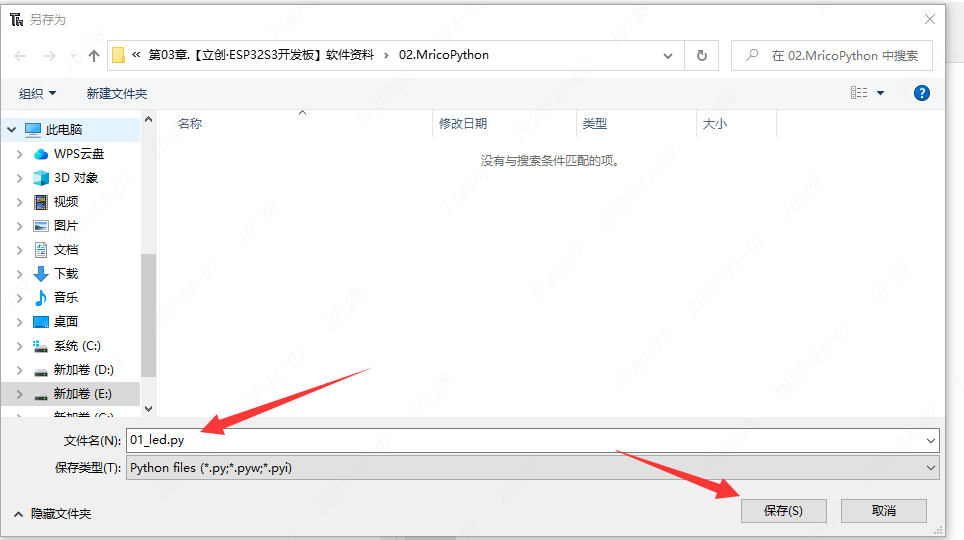
Create a new file in Thonny. 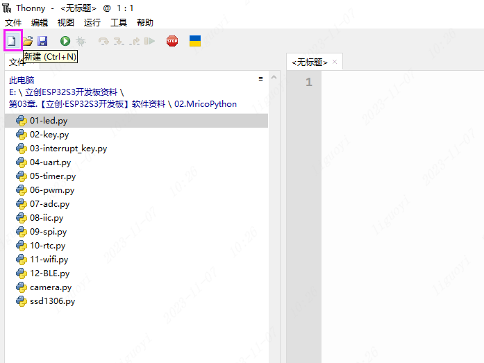 Name and save it as 01_led.py.
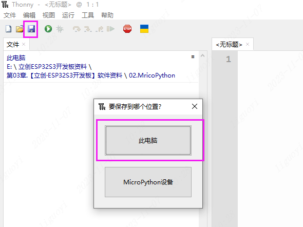
 Write the following code in 01_led.py:
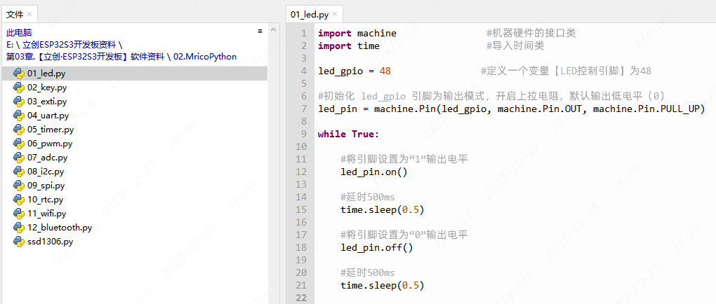
import machine                # Interface class for machine hardware
import time                   # Import the time class

led_gpio = 48                # Define a variable [LED control pin] as 48

# Initialize the led_gpio pin as output mode, enable the pull-up resistor, default output low level (0)
led_pin = machine.Pin(led_gpio, machine.Pin.OUT, machine.Pin.PULL_UP)

while True:

    # Set the pin to the "1" output level
    led_pin.on()

    # Delay 500ms
    time.sleep(0.5)

    # Set the pin to the "0" output level
    led_pin.off()

    # Delay 500ms
time.sleep(0.5)In this example, the time class is used for delay. Description:
utime.sleep(seconds)- Sleeps for the given number of seconds. ESP32S3 accepts seconds as a floating-point number to sleep for a fraction of a second. For other related delay functions, please refer to the time class in the official MicroPython documentation:
http://www.86x.org/en/latet/library/time.html
3.7 LED Blink Effect
After downloading the code, the LED marked G48 on the dev board will turn on and off in a continuous loop.