

4. Button-Controlled LED
4.1 Independent Button Basics
An independent button is a simple input device widely used in various electronic devices to implement basic user interaction. Their working principle is usually based on a simple mechanical switch that triggers certain operations when the button is pressed. Independent buttons can come in various sizes, shapes, and colors, making them easy for users to identify and use.
An independent button is a simple input device widely used in various electronic devices to implement basic user interaction. Their working principle is usually based on a simple mechanical switch that triggers certain operations when the button is pressed. Independent buttons can come in various sizes, shapes, and colors, making them easy for users to identify and use.
4.2 Independent Button Structure
The main structure of an independent button includes: the button cap, shell, spring, contacts, conductive sheet, and pins. It is composed of an elastic body (such as a spring or metal sheet) and a button cap. When the button is pressed by the user, the elastic body shortens, compressing the button cap so that the top of the button approaches or touches the base. When the user releases the button, the elastic body returns to its original state, and the button returns to its initial position. Therefore, when the button is not pressed, the contacts are usually separated and the circuit is open. When the button is pressed, the conductive sheet touches the contacts, thus forming a closed circuit. 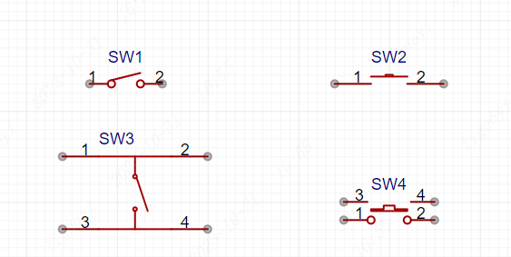
4.3 Independent Button Driving Principle
The purpose of independent button driving is to enable the microcontroller to recognize the button state. Since a microcontroller can recognize high and low levels, most buttons work by connecting one end of the button to a high level and the other end to a GPIO; or by connecting one end of the button to a low level and the other end to a GPIO. By detecting whether the level on the pin connected to the button has changed, we can know whether the button is pressed.
4.4 Debouncing Measures
Because mechanical buttons may produce mechanical vibration (similar to a spring) when closing and opening, causing the switch state to change multiple times within a short period of time, this is the button bounce phenomenon. Debouncing measures are mainly divided into software debouncing and hardware debouncing:
- Software debouncing: Mainly through programming methods, setting a delay or timer to ensure that the button state is read only once within a certain period of time, avoiding the impact of bouncing on the program.
- Hardware debouncing: Adding components such as an RC low-pass filter composed of resistors and capacitors to the button circuit to smooth the button signal and reduce the impact of bouncing.
4.5 Independent Button Schematic
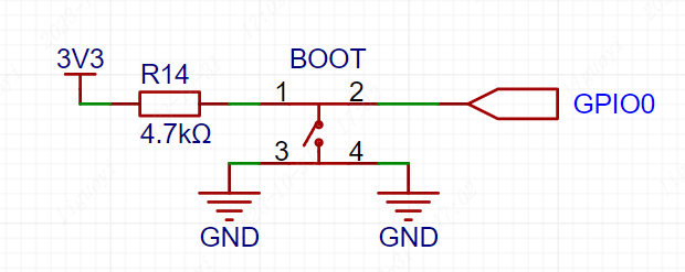
In the dev board schematic, one end of the button is connected to the 3.3V high level and the GPIO0 pin through the pull-up resistor R14, and the other end is connected to GND (low level). Simplifying the button circuit of the dev board, we get the following figure. 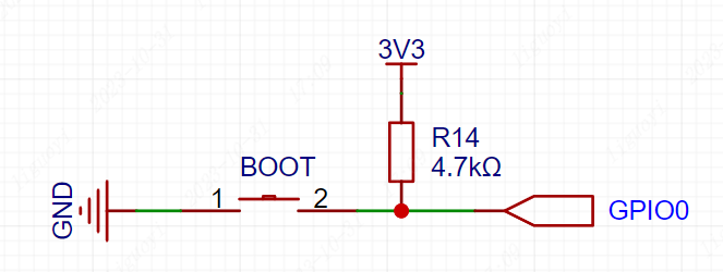
As soon as the dev board is powered on, the GPIO0 pin becomes high level due to the pull-up resistor R14. Therefore, when the button is not pressed, the GPIO0 pin defaults to high level; when the button is pressed, because the button closes, GPIO0 is connected to GND through the button, so GPIO0 becomes low level. Therefore, in the code, we continuously detect the level state of the button. When a low level is detected, it means the button is pressed; when a high level is detected, it means the button is not pressed.
4.6 Independent Button Driving Process
The following is a simplified independent button driving process:
- Import the interface class
from machine import Pin # Interface class for machine hardwareIn the previous LED chapter, we directly imported the machine class, which caused us to add the class path every time we used other features later, for example, to initialize a pin:
classmachine.Pin(id, mode=- 1, pull=- 1, *, value, drive, alt)If we import a specific class, such as Pin under machine.
from machine import Pin # Interface class for machine hardwareWhen initializing the pin, we can write it like this: Pin(id, mode=- 1, pull=- 1, *, value, drive, alt)
- Initialize the microcontroller's GPIO as an input function
key_gpio = 0
# Initialize the key_gpio pin as input mode, enable the pull-up resistor
key_pin = machine.Pin(key_gpio, machine.Pin.IN, Pin.PULL_UP)- Detect button state (timed polling or interrupt trigger) Pin.value(x) is a function in MicroPython programming used to read the level state from a pin or set the pin to output a corresponding value. When the pin is set to input mode (Pin.IN), you can use this function to read the current level state of the pin. Pin.value(x) This method allows setting and getting the value of the pin, depending on whether the parameter x is provided. If the x parameter is not provided, this method gets the digital logic level of the pin, returning 0 or 1 corresponding to low and high level signals respectively. Whether the obtained value is correct also depends on the mode of the pin:
- Pin.IN - When the pin is in input mode, this method returns the actual input value currently present on the pin, high or low level.
- Pin.OUT - When the pin is in output mode, this method has no effect.
If the x parameter is provided, this method sets the digital logic level output of the pin. The parameter x can be anything that converts to a boolean value. If converted to True, the pin is set to state "1", that is, output high level; otherwise, it is set to state "0", that is, output low level. Note that when setting a value, this method returns None.
What is timed polling or interrupt trigger?
- Timed polling, also called sequential detection, is a scanning-style button driving method that detects the button state in a loop within cyclical code. When the button closure is detected, the corresponding operation is performed.
- Interrupt trigger mainly uses the interrupt function of the microcontroller. When the button state changes, the microcontroller responds immediately, stops the current task, and executes the button response program. This method has high requirements for real-time performance.
- If there is bounce, apply debouncing measures
- If there is bounce, apply debouncing measures Set a delay to ensure that the button state is read only once within a certain period of time, filtering out the bounce phenomenon and avoiding the impact of bouncing on the program.
    # If the button is pressed
    if KEY.value()==0:
        # Debounce
        time.sleep_ms(10)
        # Reconfirm whether the button is pressed
if KEY.value()==0:4.7 Button-Controlled LED Verification
Initialize GPIO0, which is connected to the onboard BOOT button of the dev board, as input mode. Design a program so that pressing the button turns the LED on, and pressing it again turns the LED off.
The onboard BOOT button on the dev board can be used normally as long as it is not pressed during power-on.
from machine import Pin
import time

# Initialize GPIO48 pin as output mode
LED=Pin(48,Pin.OUT)

# Initialize GPIO0 pin as input mode, enable the pull-up resistor
KEY=Pin(0,Pin.IN,Pin.PULL_UP)

# LED state variable
state=0

while True:
    # If the button is pressed
    if KEY.value()==0:
        # Debounce
        time.sleep_ms(10)
        # Reconfirm whether the button is pressed
        if KEY.value()==0:
            # Invert the LED state variable
            state=not state
            # Toggle the LED state
            LED.value(state)
            # Wait for the button to release (if it remains 0, keep delaying)
            while not KEY.value():
time.sleep_ms(50)4.8 Button-Controlled LED Effect
Press the button to turn the LED on, press the button again to turn the LED off, and repeat.