一、模块来源
采购链接:1.14寸TFT显示屏ips液晶屏1.14寸st7789并口屏高清TFT LCD135240
资料下载链接:https://pan.baidu.com/s/1cVzawBFj3ZkGml5Dj-368A
资料提取码:8888
二、规格参数
工作电压:3.3V
工作电流:20MA
模块尺寸:31.4(H) x 28(V) MM
像素大小:135(H) x 240(V)RGB
驱动芯片:ST7789V
通信协议:8位并口
管脚数量:16 Pin(2.54mm间距排针)
以上信息见厂家资料文件【ZJY096S0800TG01.pdf】
三、移植过程
我们的目标是将例程移植至开发板上。按照以下步骤,即可完成移植。
- 将源码导入工程;
- 根据编译报错处进行粗改;
- 修改引脚配置;
- 修改时序配置;
- 移植验证。
1、查看资料
打开厂家资料例程(例程下载见百度网盘链接下载)。具体路径见例程路径
2、移植至工程
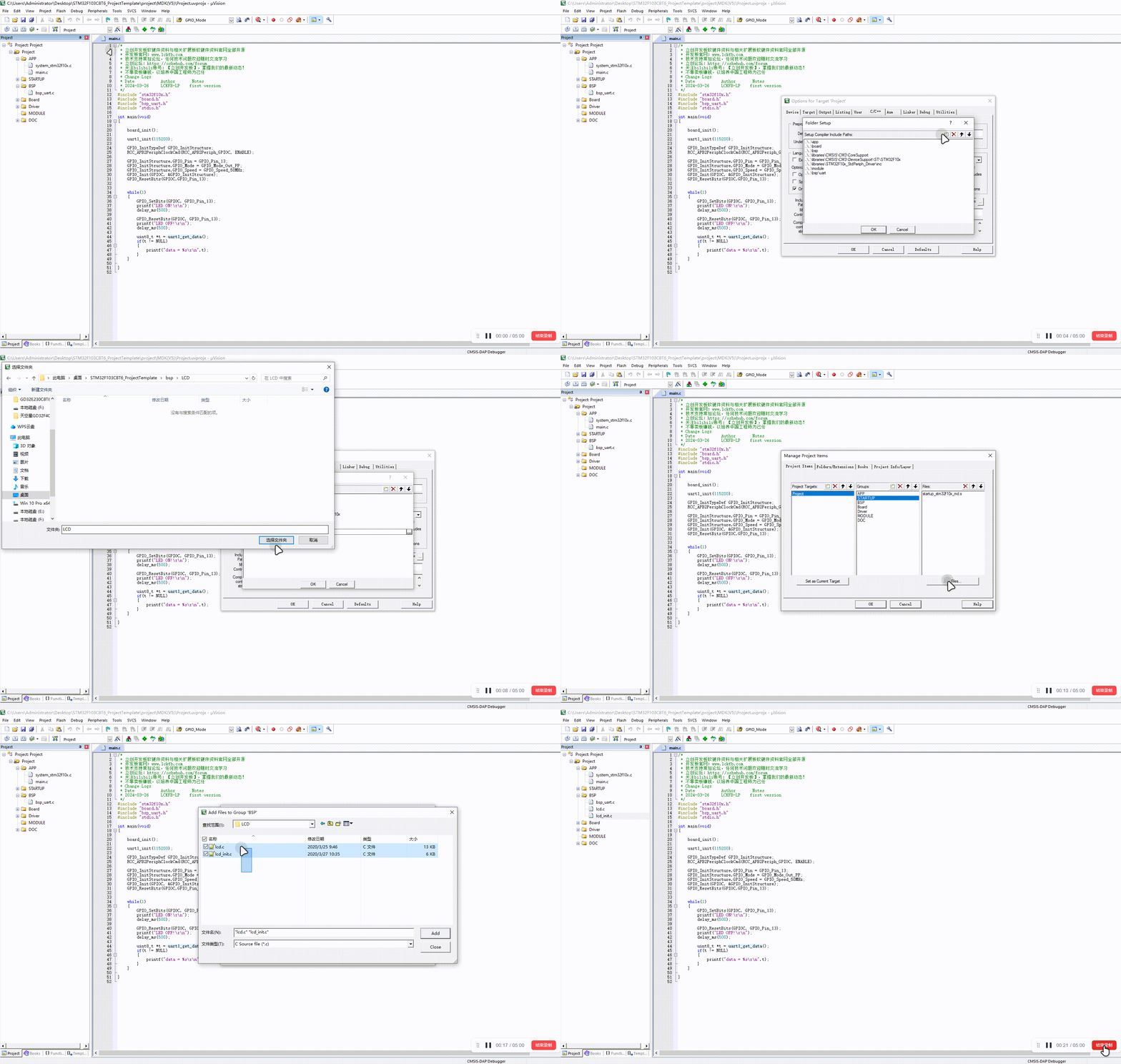
将厂家资料路径下的【LCD】文件夹,复制到自己的工程中。(工程可以参考入门手册工程模板)
我们打开工程文件,将我们刚刚复制到文件夹中的文件,导入C文件和路径。

将lcd_init.h文件下的 sys.h 改为 stm32f10x.h,还要将lcd.h文件下的 sys.h 改为 stm32f10x.h。
TIP
(在左边将lcd.c和lcd_init.c的工程目录展开,就发现有lcd_init.h和lcd.h)
将lcd_init.c文件下的 delay.h 改为 board.h,还要将lcd.c文件下的 delay.h 改为 board.h。
首先分别在lcd_init.h与lcd.h文件中定义三个宏,u32、u16与u8。
#ifndef u8
#define u8 uint8_t
#endif

#ifndef u16
#define u16 uint16_t
#endif

#ifndef u32
#define u32 uint32_t
#endif2
3
4
5
6
7
8
9
10
11
3、引脚选择
该屏幕需要设置8个接口,具体接口说明见 各引脚说明。
移植
因为使用的是软件并行口,所以除了特殊引脚外,其他引脚都可以设置。时序部分厂家已经完成,我们只需要将引脚和延时配置好即可。所以对应接入的屏幕引脚请按照你的需要。
选择好引脚后,进入工程开始编写屏幕引脚初始化代码。
为了方便后续移植,我在lcd_init.h处宏定义了每一个引脚,后续根据需要进行修改即可。
//-----------------LCD端口移植----------------
// 1-VCC    --3.3V
// 2-GND    --GND
// 3-BLK    --PA0
// 4-RES    --PA1
// 5-CS     --PA2
// 6-DC     --PA3
// 7-WR     --PA4
// 8-RD     --PA5
// 9-DB0    --PA6
//10-DB1    --PA7
//11-DB2    --PB0
//12-DB3    --PB1
//13-DB4    --PB10
//14-DB5    --PB11
//15-DB6    --PB12
//16-DB7    --PB13
#define RCC_LCD1     RCC_APB2Periph_GPIOA
#define RCC_LCD2     RCC_APB2Periph_GPIOB
//RD
#define PORT_LCD_RD    GPIOA
#define GPIO_LCD_RD    GPIO_Pin_5
//WR
#define PORT_LCD_WR    GPIOA
#define GPIO_LCD_WR    GPIO_Pin_4
//CS
#define PORT_LCD_CS     GPIOA
#define GPIO_LCD_CS     GPIO_Pin_2
//DC
#define PORT_LCD_DC     GPIOA
#define GPIO_LCD_DC     GPIO_Pin_3
//RES
#define PORT_LCD_RES    GPIOA
#define GPIO_LCD_RES    GPIO_Pin_1
//BLK
#define PORT_LCD_BLK    GPIOA
#define GPIO_LCD_BLK    GPIO_Pin_0
//DB0
#define PORT_LCD_DB0    GPIOA
#define GPIO_LCD_DB0    GPIO_Pin_6
//DB1
#define PORT_LCD_DB1    GPIOA
#define GPIO_LCD_DB1    GPIO_Pin_7
//DB2
#define PORT_LCD_DB2    GPIOB
#define GPIO_LCD_DB2    GPIO_Pin_0
//DB3
#define PORT_LCD_DB3    GPIOB
#define GPIO_LCD_DB3    GPIO_Pin_1
//DB4
#define PORT_LCD_DB4    GPIOB
#define GPIO_LCD_DB4    GPIO_Pin_10
//DB5
#define PORT_LCD_DB5    GPIOB
#define GPIO_LCD_DB5    GPIO_Pin_11
//DB6
#define PORT_LCD_DB6    GPIOB
#define GPIO_LCD_DB6    GPIO_Pin_12
//DB7
#define PORT_LCD_DB7    GPIOB
#define GPIO_LCD_DB7 GPIO_Pin_132
3
4
5
6
7
8
9
10
11
12
13
14
15
16
17
18
19
20
21
22
23
24
25
26
27
28
29
30
31
32
33
34
35
36
37
38
39
40
41
42
43
44
45
46
47
48
49
50
51
52
53
54
55
56
57
58
59
60
61
62
将lcd_init.c源代码中的void LCD_GPIO_Init(void)修改为如下代码。
void LCD_GPIO_Init(void)
{
    GPIO_InitTypeDef  GPIO_InitStructure;

    RCC_APB2PeriphClockCmd( RCC_LCD1|RCC_LCD2, ENABLE);//使能时钟

    GPIO_InitStructure.GPIO_Pin = GPIO_LCD_RD|GPIO_LCD_WR|GPIO_LCD_CS|GPIO_LCD_DC|GPIO_LCD_RES|GPIO_LCD_BLK|GPIO_LCD_DB0|GPIO_LCD_DB1;
    GPIO_InitStructure.GPIO_Mode = GPIO_Mode_Out_PP;//推挽输出模式
    GPIO_InitStructure.GPIO_Speed = GPIO_Speed_50MHz;//50MHz
    GPIO_Init(GPIOA, &GPIO_InitStructure);//初始化
    GPIO_SetBits(GPIOA,GPIO_LCD_RD|GPIO_LCD_WR|GPIO_LCD_CS|GPIO_LCD_DC|GPIO_LCD_RES|GPIO_LCD_BLK|GPIO_LCD_DB0|GPIO_LCD_DB1);

    GPIO_InitStructure.GPIO_Pin = GPIO_LCD_DB2|GPIO_LCD_DB3|GPIO_LCD_DB4|GPIO_LCD_DB5|GPIO_LCD_DB6|GPIO_LCD_DB7;
    GPIO_InitStructure.GPIO_Mode = GPIO_Mode_Out_PP;//推挽输出模式
    GPIO_InitStructure.GPIO_Speed = GPIO_Speed_50MHz;//50MHz
    GPIO_Init(GPIOB, &GPIO_InitStructure);//初始化
    GPIO_SetBits(GPIOB,GPIO_LCD_DB2|GPIO_LCD_DB3|GPIO_LCD_DB4|GPIO_LCD_DB5|GPIO_LCD_DB6|GPIO_LCD_DB7);

}2
3
4
5
6
7
8
9
10
11
12
13
14
15
16
17
18
19
20
将lcd_init.h中的 LCD端口定义 宏,修改为:
//-----------------LCD端口定义----------------

#define        LCD_RES_Set()       GPIO_WriteBit(PORT_LCD_RES, GPIO_LCD_RES, Bit_SET)//RES
#define        LCD_CS_Set()        GPIO_WriteBit(PORT_LCD_CS, GPIO_LCD_CS, Bit_SET)//CS
#define        LCD_DC_Set()        GPIO_WriteBit(PORT_LCD_DC, GPIO_LCD_DC, Bit_SET)//DC
#define        LCD_WR_Set()        GPIO_WriteBit(PORT_LCD_WR, GPIO_LCD_WR, Bit_SET)//WR
#define        LCD_RD_Set()        GPIO_WriteBit(PORT_LCD_RD, GPIO_LCD_RD, Bit_SET)//RD
#define        LCD_BLK_Set()       GPIO_WriteBit(PORT_LCD_BLK, GPIO_LCD_BLK, Bit_SET)//BLK

#define        LCD_RES_Clr()       GPIO_WriteBit(PORT_LCD_RES, GPIO_LCD_RES, Bit_RESET)//RES
#define        LCD_CS_Clr()        GPIO_WriteBit(PORT_LCD_CS, GPIO_LCD_CS, Bit_RESET)//CS
#define        LCD_DC_Clr()        GPIO_WriteBit(PORT_LCD_DC, GPIO_LCD_DC, Bit_RESET)//DC
#define        LCD_WR_Clr()        GPIO_WriteBit(PORT_LCD_WR, GPIO_LCD_WR, Bit_RESET)//WR
#define        LCD_RD_Clr()        GPIO_WriteBit(PORT_LCD_RD, GPIO_LCD_RD, Bit_RESET)//RD
#define LCD_BLK_Clr() GPIO_WriteBit(PORT_LCD_BLK, GPIO_LCD_BLK, Bit_RESET)//BLK2
3
4
5
6
7
8
9
10
11
12
13
14
15
16
因为是并口屏,传输8位的数据,是一根线一个位,8个位数据就是8根线。所以我们需要将一个8位的数据,装载到8根数据线上。
在 lcd_init.h 中添加以下代码,方便后续的数据传输和端口修改。
// x ? 置1 : 置0
#define BIT_DB7(x) { GPIO_WriteBit( PORT_LCD_DB7, GPIO_LCD_DB7, x?Bit_SET:Bit_RESET); }
#define BIT_DB6(x) { GPIO_WriteBit( PORT_LCD_DB6, GPIO_LCD_DB6, x?Bit_SET:Bit_RESET); }
#define BIT_DB5(x) { GPIO_WriteBit( PORT_LCD_DB5, GPIO_LCD_DB5, x?Bit_SET:Bit_RESET); }
#define BIT_DB4(x) { GPIO_WriteBit( PORT_LCD_DB4, GPIO_LCD_DB4, x?Bit_SET:Bit_RESET); }
#define BIT_DB3(x) { GPIO_WriteBit( PORT_LCD_DB3, GPIO_LCD_DB3, x?Bit_SET:Bit_RESET); }
#define BIT_DB2(x) { GPIO_WriteBit( PORT_LCD_DB2, GPIO_LCD_DB2, x?Bit_SET:Bit_RESET); }
#define BIT_DB1(x) { GPIO_WriteBit( PORT_LCD_DB1, GPIO_LCD_DB1, x?Bit_SET:Bit_RESET); }
#define BIT_DB0(x) { GPIO_WriteBit( PORT_LCD_DB0, GPIO_LCD_DB0, x?Bit_SET:Bit_RESET); }2
3
4
5
6
7
8
9
10
在 lcd_init.c 文件中,找到 void LCD_Writ_Bus(u8 dat) 函数,将其修改如下。
void LCD_Writ_Bus(u8 dat)
{
        LCD_CS_Clr();
        LCD_WR_Clr();

        BIT_DB7( (dat>>7)&0x01 );
        BIT_DB6( (dat>>6)&0x01 );
        BIT_DB5( (dat>>5)&0x01 );
        BIT_DB4( (dat>>4)&0x01 );
        BIT_DB3( (dat>>3)&0x01 );
        BIT_DB2( (dat>>2)&0x01 );
        BIT_DB1( (dat>>1)&0x01 );
        BIT_DB0( (dat>>0)&0x01 );

        LCD_WR_Set();
        LCD_CS_Set();
}2
3
4
5
6
7
8
9
10
11
12
13
14
15
16
17
18
到这里就移植完成了。
四、移植验证
在main.c中输入代码如下:
/*
 * 立创开发板软硬件资料与相关扩展板软硬件资料官网全部开源
 * 开发板官网:www.lckfb.com
 * 技术支持常驻论坛,任何技术问题欢迎随时交流学习
 * 立创论坛:https://oshwhub.com/forum
 * 关注bilibili账号:【立创开发板】,掌握我们的最新动态!
 * 不靠卖板赚钱,以培养中国工程师为己任
 * Change Logs:
 * Date           Author       Notes
 * 2024-03-28     LCKFB-LP    first version
 */
#include "stm32f10x.h"
#include "board.h"
#include "bsp_uart.h"
#include "stdio.h"
#include "lcd_init.h"
#include "lcd.h"
#include "pic.h"

int main(void)
{

    board_init();

    uart1_init(115200);

    LCD_Init();//LCD初始化
    LCD_Fill(0,0,LCD_W,LCD_H,WHITE);

    float t = 0;
    while(1)
    {
        LCD_ShowString(24,30,(uint8_t *)"LCD_W:",RED,WHITE,16,0);
        LCD_ShowIntNum(72,30,LCD_W,3,RED,WHITE,16);
        LCD_ShowString(24,50,(uint8_t *)"LCD_H:",RED,WHITE,16,0);
        LCD_ShowIntNum(72,50,LCD_H,3,RED,WHITE,16);
        LCD_ShowFloatNum1(20,80,t,4,RED,WHITE,16);
        t+=0.11;
        LCD_ShowPicture(65,80,40,40,gImage_1);

        delay_ms(1000);
    }

}2
3
4
5
6
7
8
9
10
11
12
13
14
15
16
17
18
19
20
21
22
23
24
25
26
27
28
29
30
31
32
33
34
35
36
37
38
39
40
41
42
43
44
45
上电效果: