一、模块来源
采购链接:2.2寸/2.4/2.8/3.2/3.5/4.0寸TFT触摸彩色SPI串口液晶屏显示模块
资料下载链接:http://www.lcdwiki.com/zh/3.5inch_SPI_Module_ILI9488_SKU:MSP3520
二、规格参数
工作电压:3.3V
工作电流:20MA
模块尺寸:56.34(H) x 98.00(W)
像素大小:320(H) x 480(V)RGB
驱动芯片:ILI9488
通信协议:SPI
使用管脚数量:14 Pin(2.54mm间距排针)
以上信息见厂家资料文件
三、移植过程
我们的目标是将例程移植至开发板上。按照以下步骤,即可完成移植。
- 将源码导入工程;
- 根据编译报错处进行粗改;
- 修改引脚配置;
- 修改时序配置;
- 移植验证。
1、查看资料
打开厂家资料例程(例程下载见百度网盘链接下载)。具体路径见例程路径
2、移植至工程
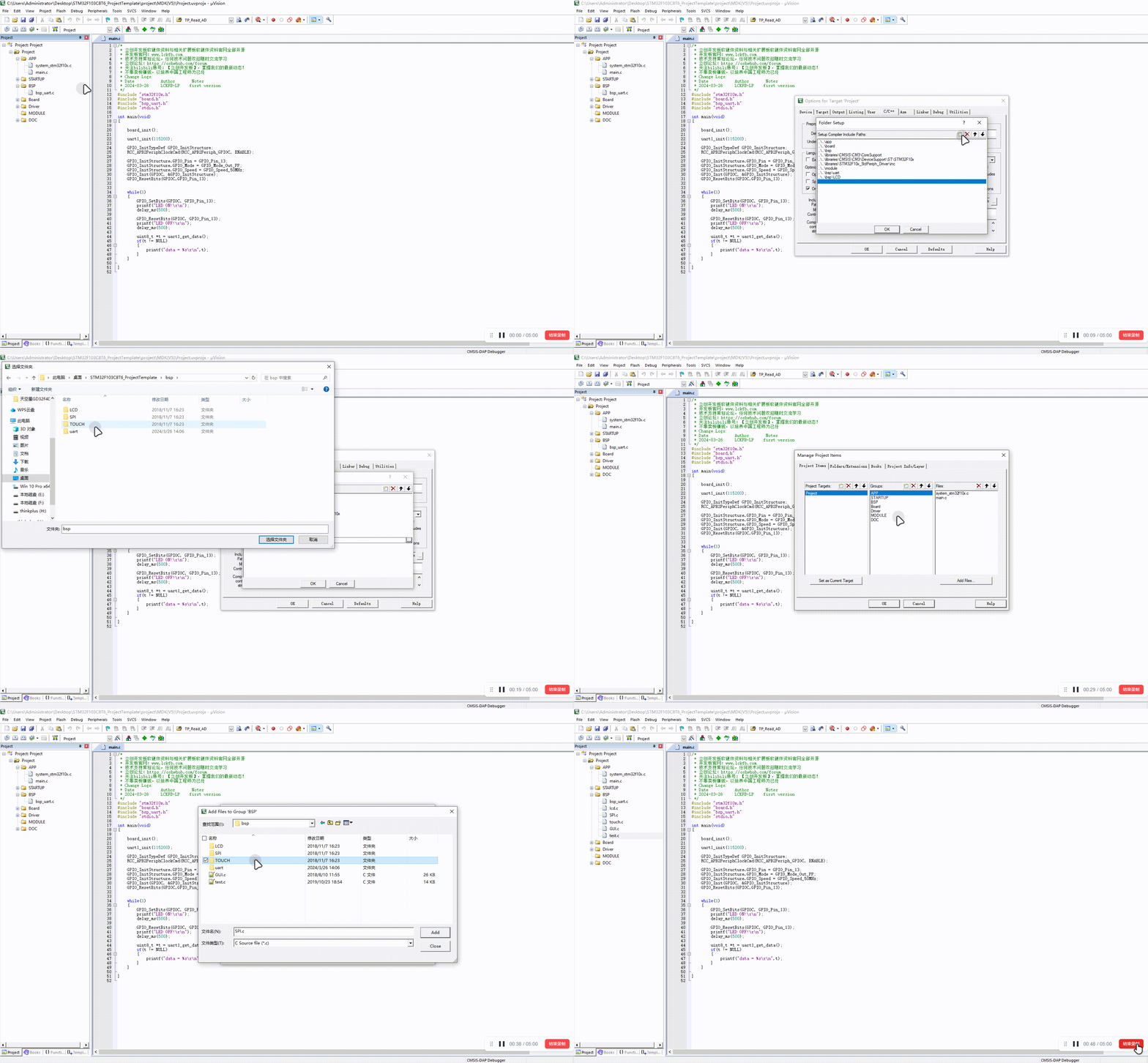
将厂家资料路径下的【LCD】文件夹,复制到自己的工程中。(工程可以参考入门手册工程模板)
复制文件夹1:
复制文件夹2:
我们打开工程文件,将我们刚刚复制到文件夹中的文件,导入C文件和路径。

在本次移植中需要用到位带操作的sys.h文件,sys.h的内容主要是位带操作部分,sys.h文件请看入门手册位带操作章节!
将sys.h文件复制到工程的board目录下。
分别在lcd.h、touch.h 和 spi.h文件中定义三个宏,u32、u16与u8。
#include "stm32f10x.h"

#ifndef u8
#define u8 uint8_t
#endif

#ifndef u16
#define u16 uint16_t
#endif

#ifndef u32
#define u32 uint32_t
#endif2
3
4
5
6
7
8
9
10
11
12
13
14
将test.c、lcd.c、touch.c和GUI.c文件中的头文件delay.h改为自己的延时函数头文件,这里我使用的是board.h;
移植
当前厂家源码使用的是软件SPI接口,SPI时序部分厂家已经完成,我们只需要将硬件SPI引脚时序和延时配置好即可。所以对应接入的屏幕引脚请按照你的需要。
为了方便后续移植,我在lcd.h处宏定义了每一个引脚,后续根据需要进行修改即可。
将lcd.c源代码中的void LCD_GPIOInit(void)修改为如下代码。
代码中已经做了引脚SPI的适配,如果没有修改相关引脚,则将宏定义USE_HARDWARE_SPI 宏 为1即可。
void LCD_GPIOInit(void)
{
    GPIO_InitTypeDef  GPIO_InitStructure;

    RCC_APB2PeriphClockCmd(RCC_LCD1|RCC_LCD2 ,ENABLE);

    GPIO_InitStructure.GPIO_Pin =   GPIO_LCD_SCL|GPIO_LCD_SDA|GPIO_LCD_BLK;
    GPIO_InitStructure.GPIO_Mode  = GPIO_Mode_Out_PP;//推挽输出模式
    GPIO_InitStructure.GPIO_Speed = GPIO_Speed_50MHz;
    GPIO_Init(GPIOA, &GPIO_InitStructure);

    GPIO_InitStructure.GPIO_Pin = GPIO_LCD_DC|GPIO_LCD_RES|GPIO_LCD_CS;
    GPIO_InitStructure.GPIO_Mode = GPIO_Mode_Out_PP;//推挽输出模式
    GPIO_Init(GPIOB, &GPIO_InitStructure);
}2
3
4
5
6
7
8
9
10
11
12
13
14
15
16
将lcd.h中的 LCD端口定义 宏,修改为:
//液晶控制口置1操作语句宏定义
#define        LCD_CS_SET          GPIO_WriteBit(PORT_LCD_CS, GPIO_LCD_CS, Bit_SET)
#define        LCD_RS_SET          GPIO_WriteBit(PORT_LCD_DC, GPIO_LCD_DC, Bit_SET)
#define        LCD_SDA_SET         GPIO_WriteBit(PORT_LCD_SDA, GPIO_LCD_SDA, Bit_SET)
#define        LCD_SCL_SET         GPIO_WriteBit(PORT_LCD_SCL, GPIO_LCD_SCL, Bit_SET)
#define        LCD_RST_SET         GPIO_WriteBit(PORT_LCD_RES, GPIO_LCD_RES, Bit_SET)
#define        LCD_LED_SET         GPIO_WriteBit(PORT_LCD_BLK, GPIO_LCD_BLK, Bit_SET)

//液晶控制口置0操作语句宏定义
#define        LCD_CS_CLR          GPIO_WriteBit(PORT_LCD_CS, GPIO_LCD_CS, Bit_RESET)//CS
#define        LCD_RS_CLR          GPIO_WriteBit(PORT_LCD_DC, GPIO_LCD_DC, Bit_RESET)//DC
#define        LCD_SDA_CLR         GPIO_WriteBit(PORT_LCD_SDA, GPIO_LCD_SDA, Bit_RESET)//SDA=MOSI
#define        LCD_SCL_CLR         GPIO_WriteBit(PORT_LCD_SCL, GPIO_LCD_SCL, Bit_RESET)//SCL=SCLK
#define        LCD_RST_CLR         GPIO_WriteBit(PORT_LCD_RES, GPIO_LCD_RES, Bit_RESET)//RES
#define LCD_LED_CLR GPIO_WriteBit(PORT_LCD_BLK, GPIO_LCD_BLK, Bit_RESET)2
3
4
5
6
7
8
9
10
11
12
13
14
15
16
在 SPI.c 文件中,找到void SPIv_WriteData(unsigned char Data) 函数,将其修改如下。
void  SPIv_WriteData(u8 Data)
{
    unsigned char i=0;
    for(i=8;i>0;i--)
    {
        if(Data&0x80)
                LCD_SDA_SET; //输出数据
        else
                LCD_SDA_CLR;

        LCD_SCL_CLR;
        LCD_SCL_SET;
        Data<<=1;
    }
}2
3
4
5
6
7
8
9
10
11
12
13
14
15
16
在spi.h中,厂家定义了关于SPI接口的宏,这里我们将其注释,使用我们自己的方式。
打开touch.c 文件 修改以下内容:
- 修改u8 TP_Init(void);函数
u8 TP_Init(void)
{
    RCC_APB2PeriphClockCmd(RCC_LCD1|RCC_LCD2 ,ENABLE);

    GPIO_InitTypeDef  GPIO_InitStructure;

    /* PEN */
    GPIO_InitStructure.GPIO_Pin   = GPIO_LCD_PEN;
    GPIO_InitStructure.GPIO_Mode  = GPIO_Mode_IPU; // 上拉输入
    GPIO_InitStructure.GPIO_Speed = GPIO_Speed_50MHz;
    GPIO_Init(PORT_LCD_PEN, &GPIO_InitStructure);

    /* DOUT*/
    GPIO_InitStructure.GPIO_Pin   = GPIO_LCD_TD0;
    GPIO_InitStructure.GPIO_Mode  = GPIO_Mode_IPU; // 上拉输入
    GPIO_InitStructure.GPIO_Speed = GPIO_Speed_50MHz;
    GPIO_Init(PORT_LCD_TD0, &GPIO_InitStructure);

    /* TDIN*/
    GPIO_InitStructure.GPIO_Pin   = GPIO_LCD_TDIN;
    GPIO_InitStructure.GPIO_Mode  = GPIO_Mode_Out_PP;//推挽输出模式
    GPIO_InitStructure.GPIO_Speed = GPIO_Speed_50MHz;
    GPIO_Init(PORT_LCD_TDIN, &GPIO_InitStructure);

    /* TCLK*/
    GPIO_InitStructure.GPIO_Pin   = GPIO_LCD_TCLK;
    GPIO_InitStructure.GPIO_Mode  = GPIO_Mode_Out_PP;//推挽输出模式
    GPIO_InitStructure.GPIO_Speed = GPIO_Speed_50MHz;
    GPIO_Init(PORT_LCD_TCLK, &GPIO_InitStructure);

    /* TCS*/
    GPIO_InitStructure.GPIO_Pin   = GPIO_LCD_CS2;
    GPIO_InitStructure.GPIO_Mode  = GPIO_Mode_Out_PP;//推挽输出模式
    GPIO_InitStructure.GPIO_Speed = GPIO_Speed_50MHz;
    GPIO_Init(PORT_LCD_CS2, &GPIO_InitStructure);

    TP_Read_XY(&tp_dev.x,&tp_dev.y);//第一次读取初始化
    return 1;
}2
3
4
5
6
7
8
9
10
11
12
13
14
15
16
17
18
19
20
21
22
23
24
25
26
27
28
29
30
31
32
33
34
35
36
37
38
39
40
- 注释掉 void TP_Save_Adjdata(void);和 u8 TP_Get_Adjdata(void);函数。
- 找到 void TP_Adjust(void) ;函数将函数里面的 TP_Save_Adjdata();和TP_Get_Adjdata();注释掉。
我们打开 test.c 文件进行一些修改:找到 void Touch_Test(void); 函数,将里面的一些语句注释掉,并且将282行括号内的 key==1 改为 1。
- 找到
打开 lcd.c 文件 找到 void LCD_Init(void); 函数将里面的LCD_LED=1;替换成 LCD_LED_SET;
打开 touch.h 文件 将里面一部分代码改为下面的部分:
//与触摸屏芯片连接引脚
//与触摸屏芯片连接引脚
#define PEN   PAin(0)    //T_PEN
#define DOUT  PAin(1)    //T_MISO
#define TDIN  PAout(2)   //T_MOSI
#define TCLK  PAout(4)   //T_SCK
#define TCS PAout(3) //T_CS2
3
4
5
6
7
修改后:
四、移植验证
在main.c中输入代码如下:
/*
 * 立创开发板软硬件资料与相关扩展板软硬件资料官网全部开源
 * 开发板官网:www.lckfb.com
 * 技术支持常驻论坛,任何技术问题欢迎随时交流学习
 * 立创论坛:https://oshwhub.com/forum
 * 关注bilibili账号:【立创开发板】,掌握我们的最新动态!
 * 不靠卖板赚钱,以培养中国工程师为己任
 * Change Logs:
 * Date           Author       Notes
 * 2024-03-28     LCKFB-LP    first version
 */
#include "stm32f10x.h"
#include "board.h"
#include "bsp_uart.h"
#include "stdio.h"
#include "Lcd.h"
#include "gui.h"
#include "test.h"
#include "spi.h"
#include "touch.h"

int main(void)
{

    board_init();

    uart1_init(115200);

    LCD_Init();   //液晶屏初始化

    while(1)
    {
        main_test();            //测试主界面
        Test_Color();           //简单刷屏填充测试
        Test_FillRec();         //GUI矩形绘图测试
        Test_Circle();          //GUI画圆测试
        Test_Triangle();        //GUI三角形绘图测试
        English_Font_test();    //英文字体示例测试
        Chinese_Font_test();    //中文字体示例测试
        Pic_test();             //图片显示示例测试
        Rotate_Test();          //旋转显示测试

        //如果不带触摸,或者不需要触摸功能,请注释掉下面触摸屏测试项
        Touch_Test();           //触摸屏手写测试
    }

}2
3
4
5
6
7
8
9
10
11
12
13
14
15
16
17
18
19
20
21
22
23
24
25
26
27
28
29
30
31
32
33
34
35
36
37
38
39
40
41
42
43
44
45
46
47
48
上电效果: