1 本节介绍
📝本节您将学习如何通过庐山派来进行人体跌倒检测,如无特殊说明,以后所有例程的显示设备均为通过外接立创·3.1寸屏幕扩展板,在3.1寸小屏幕上显示。若用户无3.1寸屏幕扩展板也可以正常在IDE的缓冲区,只是受限于USB带宽,可能会帧率较低或卡顿。
🏆学习目标
1️⃣如何用庐山派开发板去进行人体跌倒检测。
庐山派开发板的固件是存储在TF中的,模型文件已经提前写入到固件中了,所以大家只需要复制下面的代码到IDE,传递到开发板上就可以正常运行了。无需再额外拷贝,至于后面需要拷贝自己训练的模型那就是后话了。
本文主要介绍如何在庐山派开发板上进行人体跌倒检测。可以用于多种场景(如老人看护、智慧医疗、安防监控等),实时检测并识别人体是否发生跌倒对于及时预警具有重要意义。尤其是当前我们正在步入老龄化社会,老人摔倒后的及时警告是有很大的实际意义的。
2 代码例程
python
from libs.PipeLine import PipeLine, ScopedTiming
from libs.AIBase import AIBase
from libs.AI2D import Ai2d
import os
import ujson
from media.media import *
from time import *
import nncase_runtime as nn
import ulab.numpy as np
import time
import utime
import image
import random
import gc
import sys
import aicube

# 自定义跌倒检测类,继承自AIBase基类
class FallDetectionApp(AIBase):
    def __init__(self, kmodel_path, model_input_size, labels, anchors, confidence_threshold=0.2, nms_threshold=0.5, nms_option=False, strides=[8,16,32], rgb888p_size=[224,224], display_size=[1920,1080], debug_mode=0):
        super().__init__(kmodel_path, model_input_size, rgb888p_size, debug_mode)  # 调用基类的构造函数
        self.kmodel_path = kmodel_path                      # 模型文件路径
        self.model_input_size = model_input_size            # 模型输入分辨率
        self.labels = labels                                # 分类标签
        self.anchors = anchors                              # 锚点数据,用于跌倒检测
        self.strides = strides                              # 步长设置
        self.confidence_threshold = confidence_threshold    # 置信度阈值
        self.nms_threshold = nms_threshold                  # NMS(非极大值抑制)阈值
        self.nms_option = nms_option                        # NMS选项
        self.rgb888p_size = [ALIGN_UP(rgb888p_size[0], 16), rgb888p_size[1]]  # sensor给到AI的图像分辨率,并对宽度进行16的对齐
        self.display_size = [ALIGN_UP(display_size[0], 16), display_size[1]]  # 显示分辨率,并对宽度进行16的对齐
        self.debug_mode = debug_mode                                          # 是否开启调试模式
        self.color = [(255,0, 0, 255), (255,0, 255, 0), (255,255,0, 0), (255,255,0, 255)]  # 用于绘制不同类别的颜色
        # Ai2d实例,用于实现模型预处理
        self.ai2d = Ai2d(debug_mode)
        # 设置Ai2d的输入输出格式和类型
        self.ai2d.set_ai2d_dtype(nn.ai2d_format.NCHW_FMT, nn.ai2d_format.NCHW_FMT, np.uint8, np.uint8)

    # 配置预处理操作,这里使用了pad和resize,Ai2d支持crop/shift/pad/resize/affine,具体代码请打开/sdcard/app/libs/AI2D.py查看
    def config_preprocess(self, input_image_size=None):
        with ScopedTiming("set preprocess config", self.debug_mode > 0):                    # 计时器,如果debug_mode大于0则开启
            ai2d_input_size = input_image_size if input_image_size else self.rgb888p_size   # 初始化ai2d预处理配置,默认为sensor给到AI的尺寸,可以通过设置input_image_size自行修改输入尺寸
            top, bottom, left, right = self.get_padding_param()                             # 获取padding参数
            self.ai2d.pad([0, 0, 0, 0, top, bottom, left, right], 0, [0,0,0])               # 填充边缘
            self.ai2d.resize(nn.interp_method.tf_bilinear, nn.interp_mode.half_pixel)       # 缩放图像
            self.ai2d.build([1,3,ai2d_input_size[1],ai2d_input_size[0]],[1,3,self.model_input_size[1],self.model_input_size[0]])  # 构建预处理流程

    # 自定义当前任务的后处理,results是模型输出array的列表,这里使用了aicube库的anchorbasedet_post_process接口
    def postprocess(self, results):
        with ScopedTiming("postprocess", self.debug_mode > 0):
            dets = aicube.anchorbasedet_post_process(results[0], results[1], results[2], self.model_input_size, self.rgb888p_size, self.strides, len(self.labels), self.confidence_threshold, self.nms_threshold, self.anchors, self.nms_option)
            return dets

    # 绘制检测结果到画面上
    def draw_result(self, pl, dets):
        with ScopedTiming("display_draw", self.debug_mode > 0):
            if dets:
                pl.osd_img.clear()  # 清除OSD图像
                for det_box in dets:
                    # 计算显示分辨率下的坐标
                    x1, y1, x2, y2 = det_box[2], det_box[3], det_box[4], det_box[5]
                    w = (x2 - x1) * self.display_size[0] // self.rgb888p_size[0]
                    h = (y2 - y1) * self.display_size[1] // self.rgb888p_size[1]
                    x1 = int(x1 * self.display_size[0] // self.rgb888p_size[0])
                    y1 = int(y1 * self.display_size[1] // self.rgb888p_size[1])
                    x2 = int(x2 * self.display_size[0] // self.rgb888p_size[0])
                    y2 = int(y2 * self.display_size[1] // self.rgb888p_size[1])
                    # 绘制矩形框和类别标签
                    pl.osd_img.draw_rectangle(x1, y1, int(w), int(h), color=self.color[det_box[0]], thickness=2)
                    pl.osd_img.draw_string_advanced(x1, y1-50, 32," " + self.labels[det_box[0]] + " " + str(round(det_box[1],2)), color=self.color[det_box[0]])
            else:
                pl.osd_img.clear()

    # 获取padding参数
    def get_padding_param(self):
        dst_w = self.model_input_size[0]
        dst_h = self.model_input_size[1]
        input_width = self.rgb888p_size[0]
        input_high = self.rgb888p_size[1]
        ratio_w = dst_w / input_width
        ratio_h = dst_h / input_high
        if ratio_w < ratio_h:
            ratio = ratio_w
        else:
            ratio = ratio_h
        new_w = int(ratio * input_width)
        new_h = int(ratio * input_high)
        dw = (dst_w - new_w) / 2
        dh = (dst_h - new_h) / 2
        top = int(round(dh - 0.1))
        bottom = int(round(dh + 0.1))
        left = int(round(dw - 0.1))
        right = int(round(dw - 0.1))
        return top, bottom, left, right

if __name__ == "__main__":
    # 显示模式,默认"hdmi",可以选择"hdmi"和"lcd"
    display_mode="lcd"
    # k230保持不变,k230d可调整为[640,360]
    rgb888p_size = [1920, 1080]

    if display_mode=="hdmi":
        display_size=[1920,1080]
    else:
        display_size=[800,480]
    # 设置模型路径和其他参数
    kmodel_path = "/sdcard/examples/kmodel/yolov5n-falldown.kmodel"
    confidence_threshold = 0.3
    nms_threshold = 0.45
    labels = ["Fall","NoFall"]  # 模型输出类别名称
    anchors = [10, 13, 16, 30, 33, 23, 30, 61, 62, 45, 59, 119, 116, 90, 156, 198, 373, 326]  # anchor设置

    # 初始化PipeLine,用于图像处理流程
    pl = PipeLine(rgb888p_size=rgb888p_size, display_size=display_size, display_mode=display_mode)
    pl.create()
    # 初始化自定义跌倒检测实例
    fall_det = FallDetectionApp(kmodel_path, model_input_size=[640, 640], labels=labels, anchors=anchors, confidence_threshold=confidence_threshold, nms_threshold=nms_threshold, nms_option=False, strides=[8,16,32], rgb888p_size=rgb888p_size, display_size=display_size, debug_mode=0)
    fall_det.config_preprocess()
    try:
        while True:
            os.exitpoint()                                  # 检查是否有退出信号
            with ScopedTiming("total",1):
                img = pl.get_frame()                        # 获取当前帧数据
                res = fall_det.run(img)                     # 推理当前帧
                fall_det.draw_result(pl, res)               # 绘制结果到PipeLine的osd图像
                pl.show_image()                             # 显示当前的绘制结果
                gc.collect()                                # 垃圾回收
    except Exception as e:
        sys.print_exception(e)                              # 打印异常信息
    finally:
        fall_det.deinit()                                   # 反初始化
        pl.destroy()                                        # 销毁PipeLine实例
1
2
3
4
5
6
7
8
9
10
11
12
13
14
15
16
17
18
19
20
21
22
23
24
25
26
27
28
29
30
31
32
33
34
35
36
37
38
39
40
41
42
43
44
45
46
47
48
49
50
51
52
53
54
55
56
57
58
59
60
61
62
63
64
65
66
67
68
69
70
71
72
73
74
75
76
77
78
79
80
81
82
83
84
85
86
87
88
89
90
91
92
93
94
95
96
97
98
99
100
101
102
103
104
105
106
107
108
109
110
111
112
113
114
115
116
117
118
119
120
121
122
123
124
125
126
127
128
129
130
131
132
133
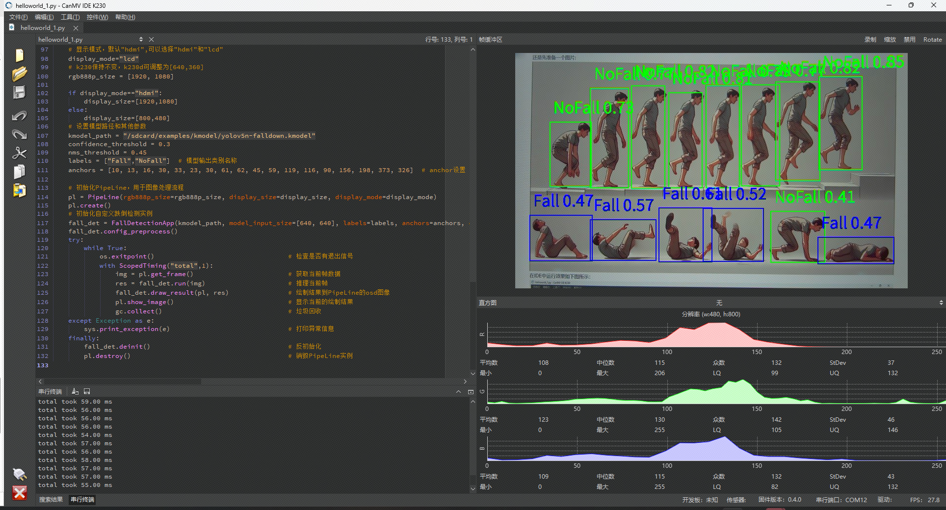
在上面的是示例中,我们使用了一个基于“YOLOv5”系列的轻量级模型(如yolov5n-falldown)来对人体跌倒姿态进行检测,会分出“Fall”和“NoFall”两个类别。通过自定义的FallDetectionApp类完成模型推理并进行可视化标注。
以上代码的主要流程如下,还是和之前的AI相关代码一样:
- 采集图像:从摄像头(默认摄像头是CSI2接口上的)获得原始图像。
- 预处理:对图像进行
resize、pad、normalize等操作,让输入满足模型的格式要求。 - 模型推理:将图像输入到训练好的人体关键点检测模型(我们这个例子里面是“yolov5n-falldown”,已经存储在TF卡里面了)得到模型输出。
- 后处理:根据模型输出获取关键点坐标、得分等信息。
- 可视化:将检测到的关键点和人体骨架连线画到屏幕或图像上,方便调试或演示。
在主循环中进行循环推理,通过while True循环来持续获取帧、推理、绘制,直到用户通过IDE手动停止或出现异常。
套路和之前的例程一样,这里就不再赘述了。
3 实际运行
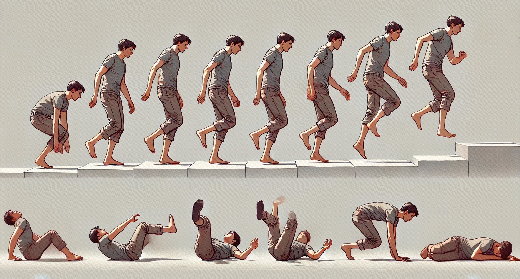
还是先准备一个图片: 
在IDE中运行效果如下图所示: 