06、I2C 总线实现 client 设备方法 *

是的,I2C在Linux中确实遵循总线设备模型,但它的设备和驱动有自己独特的命名方式。具体来说:
- 总线结构的区别 I2C直接使用真实的物理总线,不像平台总线需要虚拟一条软件总线。平台总线是为没有物理总线的设备设计的,而I2C本身就是硬件存在的通信总线,所以它有自己的总线驱动和框架。
- 为什么叫client不叫device? 在I2C体系中:
- 总线控制器称为
adapter(适配器) - 连接在总线上的设备称为
client(客户端) 这就像总线是"主服务器",设备是"客户端"的关系,所以不沿用通用的device名称。
- 实现方式演变
- 传统方式(无设备树): 需要手动编写代码注册client:
static struct i2c_device_id my_id[ ] = {

    {"my_client", 0},
    {}
};

static struct i2c_board_info __initmy_board_info(void) {
    return {
        I2C_BOARD_INFO("my_client", 0x48),  // 设备地址
    };
}

static int __init my_init(void) {
    i2c_register_board_info(0, my_board_info, 1);
    return 0;
}- 设备树方式: 在设备树里直接写:
i2c@addr {
    compatible = "my_client";
    reg = <0x48>;  // 设备地址
};驱动自动匹配,无需手动注册。
::: 总结来说:I2C设备叫client是因为总线架构特性,实现方式从早期的手动注册发展到现在的设备树自动配置,但核心都是总线模型下的设备-驱动匹配机制。 :::
一、非设备树实现 i2c client
在没有使用设备树之前,我们使用的是 i2c_board_info 这个结构体来描述一个 I2C 设备的,i2c_board_info 这个结构体如下:
struct i2c_board_info
{
        char type[I2C_NAME_SIZE]; /* I2C 设备名字 */
        unsigned short flags; /* 标志 */
        unsigned short addr; /* I2C 器件地址 */
        void *platform_data;
        struct dev_archdata *archdata;
        struct device_node *of_node;
        struct fwnode_handle *fwnode;
int irq;在这个结构体里面,type 和 addr 这两个成员变量是必须要设置的,一个是 I2C 设备的名字,这个名字就是用来进行匹配用的,一个是 I2C 设备的器件地址,也可以使用宏:
#define I2C_BOARD_INFO(dev_type, dev_addr) \
.type = dev_type, .addr = (dev_addr)I2C_BOARD_INFO宏的作用是设置i2c_board_info结构体的设备类型(type)和地址(addr)这两个关键参数。I2C设备与驱动的匹配过程由I2C核心模块负责处理,该核心模块位于Linux内核的drivers/i2c/i2c-core.c文件中,并提供了与硬件无关的通用API函数。
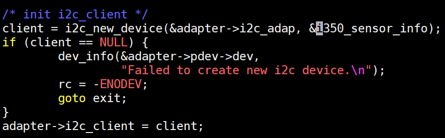
1.1、i2c_new_device
使用接收到的适配器和i2c板信息作为参数来创建i2c设备并进行注册。如果有匹配的驱动程序,它将调用该驱动程序的探针挂钩。
struct i2c_client *
i2c_new_device(struct i2c_adapter *adap, struct i2c_board_info const *info)
{
        struct i2c_client       *client;
        int                     status;

        client = kzalloc(sizeof *client, GFP_KERNEL);
        if (!client)
                return NULL;

        client->adapter = adap;

        client->dev.platform_data = info->platform_data;
        client->flags = info->flags;
        client->addr = info->addr;

        client->init_irq = info->irq;
        if (!client->init_irq)
                client->init_irq = i2c_dev_irq_from_resources(info->resources,
                                                         info->num_resources);
        client->irq = client->init_irq;

        strlcpy(client->name, info->type, sizeof(client->name));

        status = i2c_check_addr_validity(client->addr, client->flags);
        if (status) {
                dev_err(&adap->dev, "Invalid %d-bit I2C address 0x%02hx\n",
                        client->flags & I2C_CLIENT_TEN ? 10 : 7, client->addr);
                goto out_err_silent;
        }

        /* Check for address business */
        status = i2c_check_addr_ex(adap, i2c_encode_flags_to_addr(client));
        if (status)
                dev_err(&adap->dev,
                        "%d i2c clients have been registered at 0x%02x",
                        status, client->addr);

        client->dev.parent = &client->adapter->dev;
        client->dev.bus = &i2c_bus_type;
        client->dev.type = &i2c_client_type;
        client->dev.of_node = of_node_get(info->of_node);
        client->dev.fwnode = info->fwnode;

        i2c_dev_set_name(adap, client, info, status);

        if (info->properties) {
                status = device_add_properties(&client->dev, info->properties);
                if (status) {
                        dev_err(&adap->dev,
                                "Failed to add properties to client %s: %d\n",
                                client->name, status);
                        goto out_err_put_of_node;
                }
        }

        status = device_register(&client->dev);
        if (status)
                goto out_free_props;

        dev_dbg(&adap->dev, "client [%s] registered with bus id %s\n",
                client->name, dev_name(&client->dev));

        return client;

out_free_props:
        if (info->properties)
                device_remove_properties(&client->dev);
out_err_put_of_node:
        of_node_put(info->of_node);
out_err_silent:
        kfree(client);
        return NULL;
}
EXPORT_SYMBOL_GPL(i2c_new_device);i2c_new_device 实现内容:
- 用kzalloc函数在内存中申请一块空间来存放i2c_client结构体,并自动将这块空间清零。
- 把传入的i2c适配器信息保存到新结构体的适配器对应位置。
- 将预设的设备信息(包括设备地址、标志位、中断号等)从i2c_board_info结构体复制到新创建的i2c_client结构体中。
- 检查设备地址是否合法:先验证地址格式是否正确,再确认该地址没有被其他设备占用。
- 给新设备设置名称、设备树节点、属性等额外信息。
- 最后调用设备注册函数,把这个新创建的i2c设备正式添加到系统设备列表里。
整个过程就是先分配内存空间存放设备信息,填入设备参数,检查参数有效性,最后将设备注册到系统中。
1.2、i2c_client
i2c_client 结构体中还包括中断号、 I2C 控制器等信息, 该结构体定义在“include/linux/i2c.h” 文件中, 具体内容如下所示:
二、设备树实现 i2c
在使用了设备树以后,就不用这么复杂了,使用设备树的时候只要在对应的 I2C 节点下创建相应设备的节点即可,比如我想添加一个触摸芯片 FT5X06 的设备,我就可以在对应的 I2C 的节点下这样写,如下所示:
&i2c1 {
        status = "okay"
        ft5x06:ft5x06@38 {
                status = "disabled";
                 compatible = "edt,edt-ft5306";
                 reg = <0x38>;
                touch-gpio = <&gpio0 RK_PB5 IRQ_TYPE_EDGE_RISING>;
                interrupt-parent = <&gpio0>;
                interrupts = <RK_PB5 IRQ_TYPE_LEVEL_LOW>;
                reset-gpios = <&gpio0 RK_PB6 GPIO_ACTIVE_LOW>;
                touchscreen-size-x = <800>;
                touchscreen-size-y = <1280>;
                touch_type = <1>;
        };

        gt9xx:gt9xx_ts@14 {
                compatible = "goodix,gt9xx";
                reg = <0x14>;
                interrupt-parent = <&gpio0>;
                interrupts = <RK_PB5 IRQ_TYPE_LEVEL_LOW>;
                reset-gpios = <&gpio0 RK_PB6 GPIO_ACTIVE_LOW>;
                touch-gpio = <&gpio0 RK_PB5 IRQ_TYPE_EDGE_RISING>;
                status = "disabled";
                tp-size = <911>;
                max-x = <1024>;
                max-y = <600>;

        };
};- 第
3行触摸屏所使用的FT5x06芯片节点,挂载I2C-2节点下;“@”后面的“38”就是ft5x06的I2C器件地址 - 第
5行compatible用于和驱动程序的compatible匹配; - 第
6行reg属性描述ft5x的器件地址为0x38; - 第
8行interrupt-parent属性描述中断IO对应的GPIO组为GPIO0; - 第
9行interrupts属性描述中断IO对应的是GPIO0组别的B组的5号引脚; - 第
10行reset-gpios属性描述复位IO对应的GPIO0组别的B组的6号引脚;
因为我们的开发板默认是设备树的镜像, 我们进入到开发板的/sys/bus/i2c/devices/目录下,因为通过查找原理图发现我们屏幕使用的是i2c2,但这里我们要进入到 0-0038,查看 name 为 ft5x0x_ts
2.1、i2c_client 结构体的生成
2.2、i2c_driver 驱动
regulator/fan53555.c
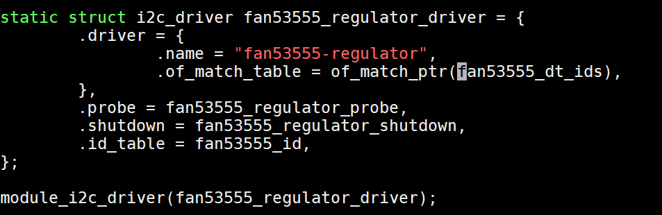
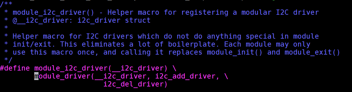
2.2.1、module_i2c_driver
linux/i2c.h
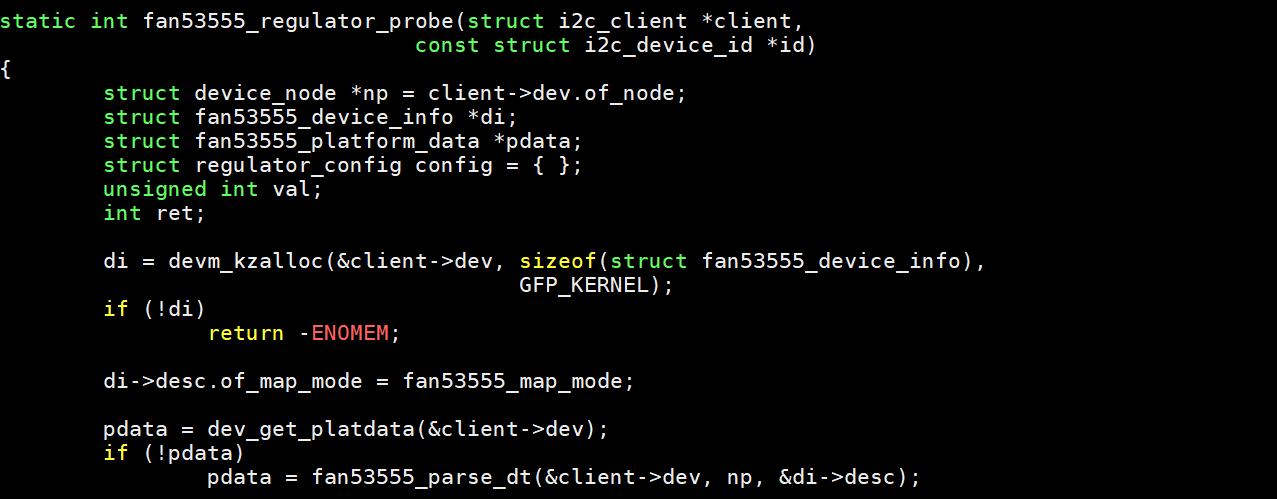
2.2.2、fan53555_regulator_probe
三、案例
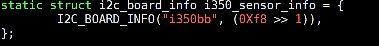
3.1、非设备树方法
net/ethernet/intel/igb/igb_hwmon.c
3.2、设备树方法