I2C配置
以 D211DC-DEMO-V1.0 开发板为例,I2C 接口3用于与触摸屏设备通信,原理图如下: 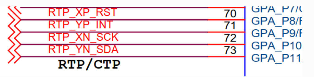
另外根据芯片手册 4 引脚复用 章节可知:
通信接口为 I2C3,Master 模式
PA8 为 RST
PA9 为 INT
PA10 为 I2C3_SCL
PA11 为 I2C3_SDA
需配置:
驱动配置
pinmux 配置
驱动配置
master 驱动使能
Board options  --->
        [ ] Using i2c0
        [ ] Using i2c1
        [ ] Using i2c2
        [*] Using i2c3
                i2c3 parameter  --->
                        [ ] Using I2C3 10-bit Addr(default 7-bit addr)
                        [ ] Using I2C3 Stand Speed(default fast speed)
[ ] Using I2C3 Slave Mode(default master mode)slave 驱动使能
Board options  --->
        [ ] Using i2c0
        [ ] Using i2c1
        [ ] Using i2c2
        [*] Using i2c3
                i2c3 parameter  --->
                        [ ] Using I2C3 10-bit Addr(default 7-bit addr)
                        [ ] Using I2C3 Stand Speed(default fast speed)
                        [*] Using I2C3 Slave Mode(default master mode)
(80) I2C3 Slave Addr注解
从机模式输入的80是10进制的,换算成16进制就是0x50
master中断模式使能
Drivers options  --->
[*] Support I2c Dev Interrupt Mode注解
如果这里不进行配置,默认是使用轮询模式进行数据传输
pinmux 配置
pinmux.c 的完整路径是 target/
根据原理图,添加如下引脚配置
c
struct aic_pinmux aic_pinmux_config[] = {
...
#ifdef AIC_USING_I2C3
    {1, PIN_PULL_DIS, 3, "PA.8"},  // RST
    {1, PIN_PULL_DIS, 3, "PA.9"},  // INT
    {4, PIN_PULL_DIS, 3, "PA.10"}, // SCK
    {4, PIN_PULL_DIS, 3, "PA.11"}, // SDA
#endif
...
}