
参考资料:
内核头文件:
include\linux_s__pi_s__pi.h内核文档:
Documentation_evicetree_indings_s__pi_s__pi-bus.txt内核源码:
drivers_s__pi_s__pi.c
一、spi_device结构体
struct spi_device {
        struct device           dev;
        struct spi_controller   *controller;
        struct spi_controller   *master;        /* compatibility layer */
        u32                     max_speed_hz;
        u8                      chip_select;
        u8                      bits_per_word;
        bool                    rt;
        u32                     mode;
#define SPI_CPHA        0x01                    /* clock phase */
#define SPI_CPOL        0x02                    /* clock polarity */
#define SPI_MODE_0      (0|0)                   /* (original MicroWire) */
#define SPI_MODE_1      (0|SPI_CPHA)
#define SPI_MODE_2      (SPI_CPOL|0)
#define SPI_MODE_3      (SPI_CPOL|SPI_CPHA)
#define SPI_CS_HIGH     0x04                    /* chipselect active high? */
#define SPI_LSB_FIRST   0x08                    /* per-word bits-on-wire */
#define SPI_3WIRE       0x10                    /* SI/SO signals shared */
#define SPI_LOOP        0x20                    /* loopback mode */
#define SPI_NO_CS       0x40                    /* 1 dev/bus, no chipselect */
#define SPI_READY       0x80                    /* slave pulls low to pause */
#define SPI_TX_DUAL     0x100                   /* transmit with 2 wires */
#define SPI_TX_QUAD     0x200                   /* transmit with 4 wires */
#define SPI_RX_DUAL     0x400                   /* receive with 2 wires */
#define SPI_RX_QUAD     0x800                   /* receive with 4 wires */
#define SPI_CS_WORD     0x1000                  /* toggle cs after each word */
#define SPI_TX_OCTAL    0x2000                  /* transmit with 8 wires */
#define SPI_RX_OCTAL    0x4000                  /* receive with 8 wires */
#define SPI_3WIRE_HIZ   0x8000                  /* high impedance turnaround */
        int                     irq;
        void                    *controller_state;
        void                    *controller_data;
        char                    modalias[SPI_NAME_SIZE];
        const char              *driver_override;
        int                     cs_gpio;        /* LEGACY: chip select gpio */
        struct gpio_desc        *cs_gpiod;      /* chip select gpio desc */
        struct spi_delay        word_delay; /* inter-word delay */

        /* the statistics */
        struct spi_statistics   statistics;

        /*
         * likely need more hooks for more protocol options affecting how
         * the controller talks to each chip, like:
         *  - memory packing (12 bit samples into low bits, others zeroed)
         *  - priority
         *  - chipselect delays
         *  - ...
         */
};各个成员含义如下:
max_speed_hz:该设备能支持的SPI时钟最大值
chip_select:是这个spi_master下的第几个设备
在spi_master中有一个cs_gpios数组,里面存放有下面各个spi设备的片选引脚
spi_device的片选引脚就是:cs_gpios_spi_device.chip_select_
cs_gpio:这是可选项,也可以把spi_device的片选引脚记录在这里
bits_per_word:每个基本的SPI传输涉及多少位
word:我们使用SPI控制器时,一般是往某个寄存器里写入数据,SPI控制器就会把这些数据一位一位地发送出去
一个寄存器是32位的,被称为一个word(有时候也称为double word)
这个寄存器里多少位会被发送出去?使用bits_per_word来表示
扩展:bits_per_word是可以大于32的,也就是每次SPI传输可能会发送多于32位的数据,这适用于DMA突发传输
mode:含义广泛,看看结构体里那些宏
SPI_CPHA:在第1个周期采样,在第2个周期采样?
SPI_CPOL:平时时钟极性
SPI_CPHA和SPI_CPOL组合起来就可以得到4种模式
SPI_MODE_0:平时SCK为低(SPI_CPOL为0),在第1个周期采样(SPI_CPHA为0)
SPI_MODE_1:平时SCK为低(SPI_CPOL为0),在第2个周期采样(SPI_CPHA为1)
SPI_MODE_2:平时SCK为高(SPI_CPOL为1),在第1个周期采样(SPI_CPHA为0)
SPI_MODE_3:平时SCK为高(SPI_CPOL为1),在第2个周期采样(SPI_CPHA为1)
SPI_CS_HIGH:一般来说片选引脚时低电平有效,SPI_CS_HIGH表示高电平有效
SPI_LSB_FIRST:
一般来说先传输MSB(最高位),SPI_LSB_FIRST表示先传LSB(最低位);
很多SPI控制器并不支持SPI_LSB_FIRST
SPI_3WIRE:SO、SI共用一条线
SPI_LOOP:回环模式,就是SO、SI连接在一起
SPI_NO_CS:只有一个SPI设备,没有片选信号,也不需要片选信号
SPI_READY:SPI从设备可以拉低信号,表示暂停、表示未就绪
SPI_TX_DUAL:发送数据时有2条信号线
SPI_TX_QUAD:发送数据时有4条信号线
SPI_RX_DUAL:接收数据时有2条信号线
SPI_RX_QUAD:接收数据时有4条信号线
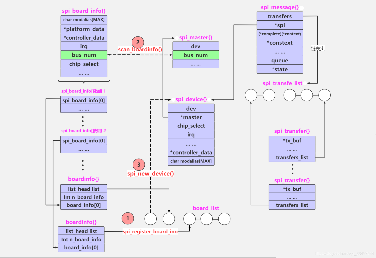
二、在开发板配置文件中实例化SPI设备(不推荐)
没有使用设备树,来对spi_devices(spi_register_board_info)
只有在系统不支持设备树的情况下,才应该在开发板文件中实例化设备。由于设备树已经出现,这种实例化方法已被弃用。因此,只要记住开发板文件驻留在arch/目录下即可。用于表示SPI设备的结构是struct spi_board_info,而不是驱动程序中使用的struct spi_device。只有当使用spi_register_board_info函数填充并注册struct spi_board_info时,内核才会构建struct spi_device(会将它传递给驱动程序,并向SPI内核注册)。
请查看include/linux/spi/spi.h中struct spi_board_info的各字段,spi_register_board_info定义在drivers/spi/spi.c中。现在来看一看某个SPI设备在开发板文件中的注册:
arm/mach-pxa/icontrol.c
static struct spi_board_info mcp251x_board_info[] = {
        {
                .modalias        = "mcp2515",
                .max_speed_hz    = 6500000,
                .bus_num         = 3,
                .chip_select     = 0,
                .platform_data   = &mcp251x_info,
                .controller_data = &mcp251x_chip_info1,
                .irq             = PXA_GPIO_TO_IRQ(ICONTROL_MCP251x_nIRQ1)
        },
        {
                .modalias        = "mcp2515",
                .max_speed_hz    = 6500000,
                .bus_num         = 3,
                .chip_select     = 1,
                .platform_data   = &mcp251x_info,
                .controller_data = &mcp251x_chip_info2,
                .irq             = PXA_GPIO_TO_IRQ(ICONTROL_MCP251x_nIRQ2)
        },
        {
                .modalias        = "mcp2515",
                .max_speed_hz    = 6500000,
                .bus_num         = 4,
                .chip_select     = 0,
                .platform_data   = &mcp251x_info,
                .controller_data = &mcp251x_chip_info3,
                .irq             = PXA_GPIO_TO_IRQ(ICONTROL_MCP251x_nIRQ3)
        },
        {
                .modalias        = "mcp2515",
                .max_speed_hz    = 6500000,
                .bus_num         = 4,
                .chip_select     = 1,
                .platform_data   = &mcp251x_info,
                .controller_data = &mcp251x_chip_info4,
                .irq             = PXA_GPIO_TO_IRQ(ICONTROL_MCP251x_nIRQ4)
        }
};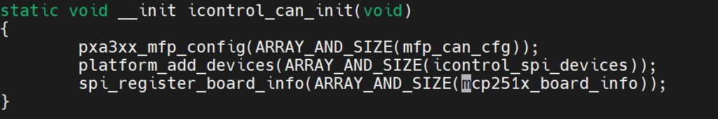
spi_register_board_info
int spi_register_board_info(struct spi_board_info const *info, unsigned n)
{
        struct boardinfo *bi;
        int i;

        if (!n)
                return 0;

        bi = kcalloc(n, sizeof(*bi), GFP_KERNEL);
        if (!bi)
                return -ENOMEM;

        for (i = 0; i < n; i++, bi++, info++) {
                struct spi_controller *ctlr;

                memcpy(&bi->board_info, info, sizeof(*info));
                if (info->properties) {
                        bi->board_info.properties =
                                        property_entries_dup(info->properties);
                        if (IS_ERR(bi->board_info.properties))
                                return PTR_ERR(bi->board_info.properties);
                }

                mutex_lock(&board_lock);
                list_add_tail(&bi->list, &board_list);
                list_for_each_entry(ctlr, &spi_controller_list, list)
                        spi_match_controller_to_boardinfo(ctlr,
                                                          &bi->board_info);
                mutex_unlock(&board_lock);
        }

        return 0;
}static void spi_match_controller_to_boardinfo(struct spi_controller *ctlr,
struct spi_board_info *bi)
{
struct spi_device *dev;
if (ctlr->bus_num != bi->bus_num)
return;
dev = spi_new_device(ctlr, bi);
if (!dev)
dev_err(ctlr->dev.parent, "can't create new device for %s\n",
bi->modalias);
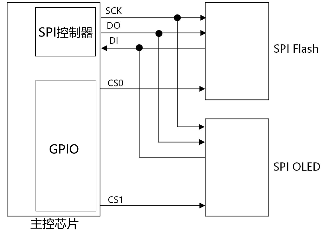
}三、SPI和设备树
与I2C设备类似,SPI设备属于DT中的非存储器映射设备系列,但也可寻址。这里,地址是指分配给控制器(主设备)的CS列表的CS索引(从0开始)。举例来说,可能有3个不同的SPI设备位于SPI总线上,每个SPI设备都有其CS线路。主设备将得到一组GPIO,每个GPIO代表CS要激活设备。如果设备X使用第二条GPIO线作为CS,则必须在reg属性中将其地址设置为1(因为始终从0开始编号)。
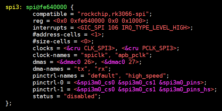
3.1、SPI设备树格式
3.2、SPI Master
在设备树中,对于SPI Master,必须的属性如下:
#address-cells:这个SPI Master下的SPI设备,需要多少个cell来表述它的片选引脚#size-cells:必须设置为0compatible:根据它找到SPI Master驱动
可选的属性如下:
cs-gpios:SPI Master可以使用多个GPIO当做片选,可以在这个属性列出那些GPIO
num-cs:片选引脚总数
其他属性都是驱动程序相关的,不同的SPI Master驱动程序要求的属性可能不一样。
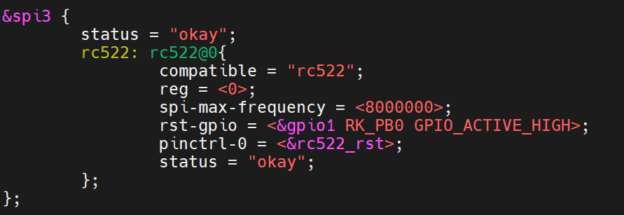
3.3、SPI Device
在SPI Master对应的设备树节点下,每一个子节点都对应一个SPI设备,这个SPI设备连接在该SPI Master下面。
这些子节点中,必选的属性如下:
compatible:根据它找到SPI Device驱动
reg:用来表示它使用哪个片选引脚
spi-max-frequency:必选,该SPI设备支持的最大SPI时钟
可选的属性如下:
spi-cpol:这是一个空属性(没有值),表示CPOL为1,即平时SPI时钟为低电平
spi-cpha:这是一个空属性(没有值),表示CPHA为1),即在时钟的第2个边沿采样数据
spi-cs-high:这是一个空属性(没有值),表示片选引脚高电平有效
spi-3wire:这是一个空属性(没有值),表示使用SPI 三线模式
spi-lsb-first:这是一个空属性(没有值),表示使用SPI传输数据时先传输最低位(LSB)
spi-tx-bus-width:表示有几条MOSI引脚;没有这个属性时默认只有1条MOSI引脚
spi-rx-bus-width:表示有几条MISO引脚;没有这个属性时默认只有1条MISO引脚
spi-rx-delay-us:单位是毫秒,表示每次
rk356x-lubancat-rk_series.dts
3.4、设备树处理过程
int spi_register_controller(struct spi_controller *ctlr)----->of_register_spi_devices
static struct spi_device *
of_register_spi_device(struct spi_controller *ctlr, struct device_node *nc)
{
        struct spi_device *spi;
        int rc;

        /* Alloc an spi_device */
        spi = spi_alloc_device(ctlr);
        if (!spi) {
                dev_err(&ctlr->dev, "spi_device alloc error for %pOF\n", nc);
                rc = -ENOMEM;
                goto err_out;
        }

        /* Select device driver */
        rc = of_modalias_node(nc, spi->modalias,
                                sizeof(spi->modalias));
        if (rc < 0) {
                dev_err(&ctlr->dev, "cannot find modalias for %pOF\n", nc);
                goto err_out;
        }

        rc = of_spi_parse_dt(ctlr, spi, nc);
        if (rc)
                goto err_out;

        /* Store a pointer to the node in the device structure */
        of_node_get(nc);
        spi->dev.of_node = nc;
        spi->dev.fwnode = of_fwnode_handle(nc);

        /* Register the new device */
        rc = spi_add_device(spi);
        if (rc) {
                dev_err(&ctlr->dev, "spi_device register error %pOF\n", nc);
                goto err_of_node_put;
        }

        return spi;

err_of_node_put:
        of_node_put(nc);
err_out:
        spi_dev_put(spi);
        return ERR_PTR(rc);
}①spi_alloc_device
struct spi_device *spi_alloc_device(struct spi_controller *ctlr)
{
        struct spi_device       *spi;

        if (!spi_controller_get(ctlr))
                return NULL;

        spi = kzalloc(sizeof(*spi), GFP_KERNEL);
        if (!spi) {
                spi_controller_put(ctlr);
                return NULL;
        }

        spi->master = spi->controller = ctlr;
        spi->dev.parent = &ctlr->dev;
        spi->dev.bus = &spi_bus_type;
        spi->dev.release = spidev_release;
        spi->cs_gpio = -ENOENT;

        spin_lock_init(&spi->statistics.lock);

        device_initialize(&spi->dev);
        return spi;
}
EXPORT_SYMBOL_GPL(spi_alloc_device);② of_modalias_node
of/base.c
int of_modalias_node(struct device_node *node, char *modalias, int len)
{
        const char *compatible, *p;
        int cplen;

        compatible = of_get_property(node, "compatible", &cplen);
        if (!compatible || strlen(compatible) > cplen)
                return -ENODEV;
        p = strchr(compatible, ',');
        strlcpy(modalias, p ? p + 1 : compatible, len);
        return 0;
}
EXPORT_SYMBOL_GPL(of_modalias_node);③ of_spi_parse_dt
static int of_spi_parse_dt(struct spi_controller *ctlr, struct spi_device *spi,
                           struct device_node *nc)
{
        u32 value;
        int rc;

        /* Mode (clock phase/polarity/etc.) */
        if (of_property_read_bool(nc, "spi-cpha"))
                spi->mode |= SPI_CPHA;
        if (of_property_read_bool(nc, "spi-cpol"))
                spi->mode |= SPI_CPOL;
        if (of_property_read_bool(nc, "spi-cs-high"))
                spi->mode |= SPI_CS_HIGH;
        if (of_property_read_bool(nc, "spi-3wire"))
                spi->mode |= SPI_3WIRE;
        if (of_property_read_bool(nc, "spi-lsb-first"))
                spi->mode |= SPI_LSB_FIRST;

        /* Device DUAL/QUAD mode */
        if (!of_property_read_u32(nc, "spi-tx-bus-width", &value)) {
                switch (value) {
                case 1:
                        break;
                case 2:
                        spi->mode |= SPI_TX_DUAL;
                        break;
                case 4:
                        spi->mode |= SPI_TX_QUAD;
                        break;
                default:
                        dev_warn(&ctlr->dev,
                                "spi-tx-bus-width %d not supported\n",
                                value);
                        break;
                }
        }

        if (!of_property_read_u32(nc, "spi-rx-bus-width", &value)) {
                switch (value) {
                case 1:
                        break;
                case 2:
                        spi->mode |= SPI_RX_DUAL;
                        break;
                case 4:
                        spi->mode |= SPI_RX_QUAD;
                        break;
                default:
                        dev_warn(&ctlr->dev,
                                "spi-rx-bus-width %d not supported\n",
                                value);
                        break;
                }
        }

        if (spi_controller_is_slave(ctlr)) {
                if (strcmp(nc->name, "slave")) {
                        dev_err(&ctlr->dev, "%pOF is not called 'slave'\n",
                                nc);
                        return -EINVAL;
                }
                return 0;
        }

        /* Device address */
        rc = of_property_read_u32(nc, "reg", &value);
        if (rc) {
                dev_err(&ctlr->dev, "%pOF has no valid 'reg' property (%d)\n",
                        nc, rc);
                return rc;
        }
        spi->chip_select = value;

        /* Device speed */
        rc = of_property_read_u32(nc, "spi-max-frequency", &value);
        if (rc) {
                dev_err(&ctlr->dev,
                        "%pOF has no valid 'spi-max-frequency' property (%d)\n", nc, rc);
                return rc;
        }
        spi->max_speed_hz = value;

        return 0;
}④ spi_add_device
spi/spi.c
/**
 * spi_add_device - Add spi_device allocated with spi_alloc_device
 * @spi: spi_device to register
 *
 * Companion function to spi_alloc_device.  Devices allocated with
 * spi_alloc_device can be added onto the spi bus with this function.
 *
 * Return: 0 on success; negative errno on failure
 */
int spi_add_device(struct spi_device *spi)
{
        struct spi_controller *ctlr = spi->controller;
        struct device *dev = ctlr->dev.parent;
        int status;

        /* Chipselects are numbered 0..max; validate. */
        if (spi->chip_select >= ctlr->num_chipselect) {
                dev_err(dev, "cs%d >= max %d\n", spi->chip_select,
                        ctlr->num_chipselect);
                return -EINVAL;
        }

        /* Set the bus ID string */
        spi_dev_set_name(spi);

        /* We need to make sure there's no other device with this
         * chipselect **BEFORE** we call setup(), else we'll trash
         * its configuration.  Lock against concurrent add() calls.
         */
        mutex_lock(&spi_add_lock);

        status = bus_for_each_dev(&spi_bus_type, NULL, spi, spi_dev_check);
        if (status) {
                dev_err(dev, "chipselect %d already in use\n",
                                spi->chip_select);
                goto done;
        }

        /* Controller may unregister concurrently */
        if (IS_ENABLED(CONFIG_SPI_DYNAMIC) &&
            !device_is_registered(&ctlr->dev)) {
                status = -ENODEV;
                goto done;
        }

        if (ctlr->cs_gpios)
                spi->cs_gpio = ctlr->cs_gpios[spi->chip_select];

        /* Drivers may modify this initial i/o setup, but will
         * normally rely on the device being setup.  Devices
         * using SPI_CS_HIGH can't coexist well otherwise...
         */
        status = spi_setup(spi);
        if (status < 0) {
                dev_err(dev, "can't setup %s, status %d\n",
                                dev_name(&spi->dev), status);
                goto done;
        }

        /* Device may be bound to an active driver when this returns */
        status = device_add(&spi->dev);
        if (status < 0)
                dev_err(dev, "can't add %s, status %d\n",
                                dev_name(&spi->dev), status);
        else
                dev_dbg(dev, "registered child %s\n", dev_name(&spi->dev));

done:
        mutex_unlock(&spi_add_lock);
        return status;
}
EXPORT_SYMBOL_GPL(spi_add_device);- spi_new_device
spi_new_device是函数spi_alloc_device和spi_add_device的结合,使用从实用性来说,最好不好单独调用spi_alloc_device和spi_add_device,而是调用这个 spi_new_device。
/**
 * spi_new_device - instantiate one new SPI device
 * @ctlr: Controller to which device is connected
 * @chip: Describes the SPI device
 * Context: can sleep
 *
 * On typical mainboards, this is purely internal; and it's not needed
 * after board init creates the hard-wired devices.  Some development
 * platforms may not be able to use spi_register_board_info though, and
 * this is exported so that for example a USB or parport based adapter
 * driver could add devices (which it would learn about out-of-band).
 *
 * Return: the new device, or NULL.
 */
struct spi_device *spi_new_device(struct spi_controller *ctlr,
                                  struct spi_board_info *chip)
{
        struct spi_device       *proxy;
        int                     status;

        /* NOTE:  caller did any chip->bus_num checks necessary.
         *
         * Also, unless we change the return value convention to use
         * error-or-pointer (not NULL-or-pointer), troubleshootability
         * suggests syslogged diagnostics are best here (ugh).
         */

        proxy = spi_alloc_device(ctlr);
        if (!proxy)
                return NULL;

        WARN_ON(strlen(chip->modalias) >= sizeof(proxy->modalias));

        proxy->chip_select = chip->chip_select;
        proxy->max_speed_hz = chip->max_speed_hz;
        proxy->mode = chip->mode;
        proxy->irq = chip->irq;
        strlcpy(proxy->modalias, chip->modalias, sizeof(proxy->modalias));
        proxy->dev.platform_data = (void *) chip->platform_data;
        proxy->controller_data = chip->controller_data;
        proxy->controller_state = NULL;

        if (chip->properties) {
                status = device_add_properties(&proxy->dev, chip->properties);
                if (status) {
                        dev_err(&ctlr->dev,
                                "failed to add properties to '%s': %d\n",
                                chip->modalias, status);
                        goto err_dev_put;
                }
        }

        status = spi_add_device(proxy);
        if (status < 0)
                goto err_remove_props;

        return proxy;

err_remove_props:
        if (chip->properties)
                device_remove_properties(&proxy->dev);
err_dev_put:
        spi_dev_put(proxy);
        return NULL;
}